Damos la bienvenida a su parte dibujo y muestra. Nuestra empresa analizará rápidamente sus dibujos y le brindará un método de mecanizado CNC y una cotización razonables..
Si eres un profesional del procesamiento de máquinas herramienta CNC., No es difícil entender las dimensiones y símbolos profesionales en los dibujos del procesamiento de piezas metálicas de precisión.. Pero si inicialmente está expuesto a la industria del mecanizado CNC, o necesitas desarrollar un proyecto, Los dibujos deslumbrantes pueden hacerte sentir muy doloroso.. Si no entiendes los dibujos, La eficiencia y eficacia de muchas cosas será difícil de garantizar.. Hoy aprenderemos a comprender los dibujos de procesamiento de piezas metálicas de precisión.:
Comprender los dibujos de mecanizado CNC de las piezas., determinar el método de mecanizado CNC apropiado, y evaluar el precio de las piezas mecanizadas.
1. El método de notación de tamaño de estructuras comunes.
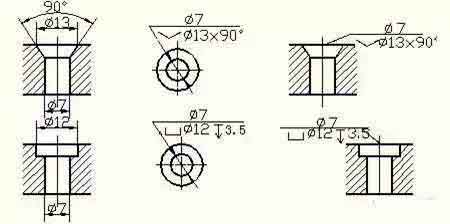
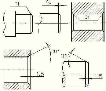
Método de inyección de tamaño de agujero común (agujero ciego, agujero roscado, avellanado, agujero avellanado); size annotation method for chamfer.

Blind hole

Threaded hole

Counterbore

Countersunk hole

Chamfer
2. Machining structure on parts
Design of undercut and overtravel grooves for CNC machining
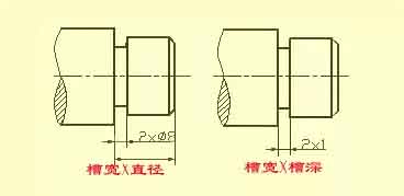
In the CNC machining of parts, in order to facilitate the withdrawal of the tool and ensure that the contact surfaces of the relevant parts are tight during assembly. The undercut or overtravel groove of the grinding wheel should be machined in advance at the step of the machined surface.
The size of the undercut when turning the outer circle can generally be marked in the way of “groove width × diameter” or “groove width × groove depth”. Grinding wheel overtravel grooves when grinding external circles and end faces.

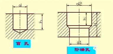
Drilling structure
The blind hole drilled with a drill has a cone angle of 120° at the bottom. It refers to the depth of the drilling depth of the cylindrical portion, excluding cone pit. At the transition of stepped boreholes, there is also a cone angle of 120° frustum, its drawing method and size injection method.
When drilling with a drill bit, the axis of the drill bit is required to be as perpendicular to the end face of the drilled hole as possible to ensure the accuracy of the drilling and avoid the drill bit from breaking. The correct structure of the three drilling end faces.

Bosses and pits
The contact surface parts and other parts, are generally required processing. In order to reduce the processing area and ensure good contact between the surface of the parts, bosses and pits are often designed on the castings. The form of the supporting surface boss or the supporting surface pit of the bolt connection;
In order to reduce the CNC machining area, a groove structure is made.
 English
 العربية
 中文(漢字)
 Čeština
 Dansk
Dansk Nederlands
 Suomi
Suomi Français
 Deutsch
 Italiano
 日本語
日本語 ಕನ್ನಡ
ಕನ್ನಡ 한국어
한국어 Português
 Русский
 Slovenčina
 Español
 Svenska
 Türkçe

