 English
 العربية
 中文(漢字)
 Čeština
 Dansk
Dansk Nederlands
 Suomi
Suomi Français
 Deutsch
 Italiano
 日本語
日本語 ಕನ್ನಡ
ಕನ್ನಡ 한국어
한국어 Português
 Русский
 Slovenčina
 Español
 Svenska
 Türkçe
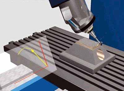
Con el aumento en el diseño de piezas curvas complejas y multifacéticas, 5-El mecanizado de ejes representará una proporción cada vez mayor del mecanizado CNC.. Porque el mecanizado CNC de 5 ejes añade dos grados de libertad de rotación, Aumenta la dificultad del cálculo de simulación de movimiento de mecanizado CNC y la verificación de interferencias de herramientas., especialmente al mecanizar piezas con formas extremadamente complejas. Por lo tanto, in order to ensure that 5-axis CNC machine tools perform high-efficiency and high-quality milling processing, the design of 5-axis machining tool path generation and interference checking software will become a major issue.
The feature projection method is suitable for 5-axis CNC machining tool interference processing, eso es, the machining surface is discretized into a series of surface feature points. Si se produce interferencia de la herramienta se puede juzgar si el punto característico ingresa al interior de la superficie de la herramienta.. Al mismo tiempo, the machining surface and the tool surface are projected onto a specific plane, and only the feature detection points in the curved surface area of the enveloping tool projection graph are checked for interference, lo que mejora la eficiencia de la detección de interferencias.
Evite la interferencia de herramientas en el fresado de 5 ejes
1. Inspection method for tool interference
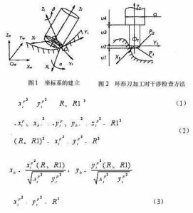
Sistema de coordenadas y transformación de coordenadas.
Como se muestra en la figura 1, the local coordinate system L of 5-axis circular cutter milling is represented as XL axis, Eje YL y eje ZL. El eje YL siempre apunta a la dirección de corte f del contacto de la herramienta. (referred to as CC point) OL. The ZL axis points to the normal direction n of the surface, and the XL axis is determined by the right-hand rule of the YL axis and the ZL axis. La herramienta generalmente gira alrededor del eje XL desde el eje ZL hasta el eje YL mediante un ángulo de avance. (ángulo del talón) a, and rotates around the ZL axis one by one side slip angle b. Además, el sistema de coordenadas de la herramienta T (xt, YouTube, ZT) También se puede definir en el punto de ubicación de la herramienta. (CL point for short) OT. The YT axis points to the direction of the line connecting the CL point and the CC point. The ZT axis is the tool axis vector direction, and the XT axis is the direction determined by the right-hand rule of the YT axis and the ZT axis. The coordinate origin is located at the tool center point (ie CL point) OT. In order to simplify the interference check, the tool surface with a relatively regular shape is used as the reference for interference check. The machined surface is discretized to express the shape of the surface in the form of a set of characteristic points. The original data of these feature points are expressed in the world coordinate system W, so the feature point data must first be transformed from the world coordinate system W (OW-XW, YW, ZW) to the local coordinate system L (OL-XL, YL, ZL) ). It is then transformed from the local coordinate system L to the tool coordinate system T (OT-XT, YouTube, ZT).
Método de verificación de interferencias
If the tool and power head have been selected, the size of the tool system (tool and power head) is known. Whether the tool system interferes with the machined surface can be determined by judging whether the characteristic point P enters the inside of the tool surface. Como se muestra en la figura 2, it is the positional relationship between the tool system and the machined surface when the ring knife is processed. In the tool coordinate system, let the coordinate of the characteristic point P be PI (Xpt, Ypt, Zpt). According to the different combination parts of the tool system, the coordinate value Zpt of the characteristic point P is divided into 4 sections for judgment. Details are as follows:
5-axis milling stroke setting formula
Cuando el punto característico P está dentro del rango de u1, no se producirá ninguna interferencia.
Cuando el punto característico P está en el rango de u2, hay dos situaciones, and the torus is divided into two parts:
The small cylindrical part P1 and the circular ring part P2. Cuando el punto característico está involucrado en la parte cilíndrica P1, se produce interferencia de la herramienta, eso es, it is satisfied
donde R representa el radio de la herramienta, y R1 representa el radio del anillo de la herramienta circular..
Cuando el punto característico está involucrado en la parte del anillo P2, También se produce interferencia con la herramienta., eso es, it is satisfied
en el estilo
If the feature point P does not enter the parts P1 and P2, no se producirá ninguna interferencia con la herramienta.
Cuando el punto característico P está dentro del rango de u3, cuando la distancia entre el punto característico P y el eje ZT es menor que el radio de la herramienta, se produce interferencia de la herramienta, que esta satisfecho
De lo contrario, no se producirá ninguna interferencia con la herramienta.
When the characteristic point P is in the range of u4, la situación es la misma que la de 3, as long as the tool radius R in the formula (3) is replaced with the power head radius d/2 for judgment.