1. Introducción
Realidad virtual, como una nueva tecnología de alta tecnología, Ha sido ampliamente utilizado en muchos campos como la aviación., aeroespacial, y fabricación. Una aplicación importante de esta tecnología es la simulación de algunos fenómenos en la industria manufacturera.. El más típico es la simulación del proceso de mecanizado CNC.. Actualmente, La tecnología de simulación basada en modelado de superficies y modelado de sólidos se ha utilizado ampliamente en la simulación CNC., y también existen buenos algoritmos para la simulación de mecanizado de una sola cara de fresadoras CNC de tres ejes..
This paper proposes a new type of real-time modification algorithm of the solid model, which can solve the realization problem of multi-face machining of CNC milling machine, and this algorithm has been well applied in the simulation software of CNC machining. This article will elaborate on the specific ideas of the multi-faceted processing algorithm and the realistic processing of graphics, and give a specific graphical description.
2. Features of CNC programming algorithm and its implementation steps:
2.1 Algorithm features of CNC programming
This method mainly uses matrix grids to construct the surface of the processed workpiece, and displays the shape of the processed object by timely modifying the depth of the node passed by the milling cutter. Al mismo tiempo, this algorithm can also easily realize the acceleration, deceleration and pause of the milling cutter, as well as the real-time zooming and rotation of the processed workpiece, providing users with different viewing angles and observation methods.
The main features of the real-time modification algorithm of the entity model we proposed are as follows:
1) The modification speed of the entity has nothing to do with the number of processing codes.
2) The calculation process is stable and reliable.
3) The display of programming calculation results has nothing to do with the observation method and the direction of the line of sight. It can zoom, rotate and pan in real time during or after the modification.
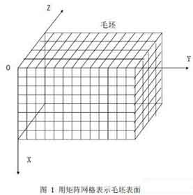
Use a matrix grid to represent the surface of the part blank
2.2 The structure definition of programming algorithm
The three-axis CNC milling machine moves on the X axis, eje y, and Z axis. The processed blank is generally a cuboid. In the computer simulation process, we choose the more commonly used flat-end milling cutter. The surface of the blank is represented as an m×n matrix grid as shown in Figure 1. Each intersection is called a node. For each node, its relative upper surface point coordinates are fixed, and what changes is its depth and the method of drawing. In the simulation process, the depth of the node is constantly changed to express the actual situation of the blank being processed. Increase the density of the matrix grid by increasing m and n, thereby improving the simulation accuracy.
First use the related linked list to save the knife drop point and its related attributes. Use a two-dimensional array to record all relevant points on each surface and the linked list information corresponding to each point. This list is used to store the starting point of this blank, vertical processed all points on a straight line to the surface. The nodes in the linked list record the coordinates of the processing points.
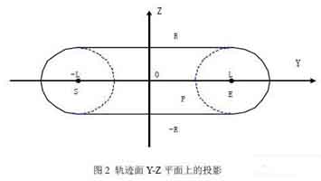
Projection on Y-Z plane of track surface
2.3 Algorithm steps:
Step1: Initialize, read in the CNC program, the attributes of the blank to be processed and the relevant information about the tool and the tool drop point, including the selection of the surface to be processed.
Step2: According to the initialization information, run the point-taking algorithm, record those points that have been processed and those points that have not been processed, eso es, node selection.
In a calculation by the computer, the milling cutter traveled a straight distance. Only those nodes on the trajectory surface should consider the modification of their depth, and call these points as modified points. If the machining surface is selected as ZOY, the flat-end milling cutter walks through a straight line, and the projection of its track surface on the X-Y plane is an area composed of a rectangle and two semicircles. In order to simplify the calculation, we can move the coordinate system as shown in Figure 2:
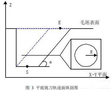
Longitudinal section of track surface of flat milling cutter
Where S is the projection of the starting point of the milling cutter on the Z-Y plane, E is the projection of the end point of the milling cutter on the Z-Y plane, the distance between S and E is 2L, and the origin is the midpoint of S and E. For any node P(y, z) that meets one of the following conditions, it becomes a modification point:
I. -R<= z <=R and -L<= y <=L
II.-R<= z <=R and | PS|<=R
III.-R<= z <=R and | EDUCACIÓN FÍSICA|<=R
Similarmente, if you choose to process other surfaces, the method is similar, except that the corresponding coordinates are changed.
Step3: Modify the depth calculation of the point
The track surface of the flat-bottom milling cutter has such a property: If the processing surface is selected as XOY, the plane z=Z0 will be a surface with radius R (como se muestra en la figura 3). Suppose the angle between SE and X-Y plane is a, and the modification point is P(X,y,z),
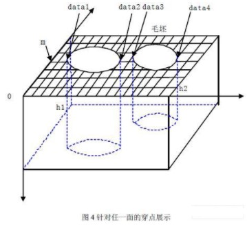
Milling display on either side of the part
Then I. If the horizontal distance between P and S is less than R, the depth of P should be the same as S.
II. If the horizontal distance between P and S is not less than R, then the depth Z of P can be obtained by the equation |(P-S)-(Z-Zs)/sinan|=R.
Similarmente, if you choose to process other surfaces, the method is similar, except that the corresponding coordinates are changed.
Step4: Connect the processed interval on each row and column on the surface of the part, and the corresponding maximum processing depth in the interval, respectively in the form of a linked list by row and a linked list by column. And record the maximum depth corresponding to the interval in the row (or column) in the head node of the corresponding linked list.

Linked list of CNC machining coordinate design
Como se muestra en la figura 4, for any face, the mth row: Assuming that in this row, the maximum depth between datal and data2 is h1, the maximum depth between data3 and data4 is h2, and h1>h2, the following linked list will be generated:
The generation of the linked list is dynamic, and it will be continuously modified as the processing progresses. Then make a hash table for each surface to record all the relevant points on each surface and the linked list of the depth point information corresponding to each point.
Step5: The drawing of parts is realized.
The process is divided into two parts: the unprocessed outer surface of the painting part and the enveloping surface formed after the painting is processed. When parts are being processed, the side boundary points of the envelope surface must be collected continuously. En este momento, the hash table information corresponding to each face is used. When drawing, according to the processing of different surfaces, the coordinates should be converted to make them appear in the same space.
2.4 Realistic processing:
The implementation tools of this algorithm are VC++6.0 and OpenGL. The matrix grid just builds the “structure” of the object. If you want to make objects realistic on the computer, you have to consider the processing of light. For each node, define a normal vector for it. By modifying the value of the normal vector while modifying the depth of the node, the light processing can be added to the simulation.
In the example described in Figure 5, the size of the blank is 300mm×300mm×200mm, and the matrix grid is 256×256. Two flat-end milling cutters with different diameters (diameters: 14mm and 6mm) son usados. The result after processing the blanks from different surfaces.
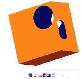
Three-sided CNC machining of parts
3 Conclusión
In NC machining simulation, in addition to the requirements for the accuracy of simulation, the machining process must be controlled at any time. In the method of this article, changing the density of the matrix grid can improve the simulation accuracy. For general needs, a density grid of 512╳512 is sufficient. Since a matrix grid is used to represent the processed workpiece, the zooming and rotating operations of the workpiece become very simple, which is beneficial to the user to observe carefully. This algorithm has been applied in practice and has achieved good results.
 English
 العربية
 中文(漢字)
 Čeština
 Dansk
Dansk Nederlands
 Suomi
Suomi Français
 Deutsch
 Italiano
 日本語
日本語 ಕನ್ನಡ
ಕನ್ನಡ 한국어
한국어 Português
 Русский
 Slovenčina
 Español
 Svenska
 Türkçe

