 English
 العربية
 中文(漢字)
 Čeština
 Dansk
Dansk Nederlands
 Suomi
Suomi Français
 Deutsch
 Italiano
 日本語
日本語 ಕನ್ನಡ
ಕನ್ನಡ 한국어
한국어 Português
 Русский
 Slovenčina
 Español
 Svenska
 Türkçe
Torneado y fresado de piezas finas (aluminio, aleación de aluminio, titanio puro, cobre, aleación de magnesio) Siempre son propensos a deformarse durante el mecanizado.. Ovalado o “forma de cintura” con extremos pequeños, medianos y grandes, lo que dificulta garantizar la calidad de las piezas. Su diseño de sujeción es a menudo el punto más discutido.. Echemos un vistazo a dos ejemplos de diseño de fijaciones de paredes delgadas en piezas de torneado y fresado., y como resuelven el problema de la deformación.
Part. 1. Design a processing plan for thin-walled aluminum sleeve parts on a milling machine
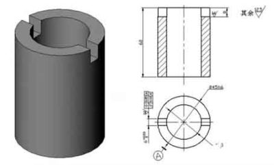
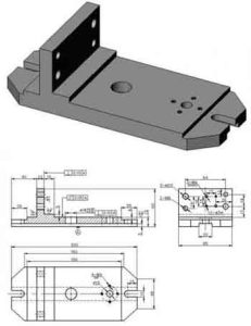
The aluminum thin-walled sleeve workpiece is shown in the figure, and the keyway width of 6mm is guaranteed by the keyway milling cutter; Grooves on both sides of a plane of symmetry axis of symmetry φ45 h6 0.05mm, 0.10mm parallelism; The groove depth is 8mm.
Milling process of aluminum thin sleeve
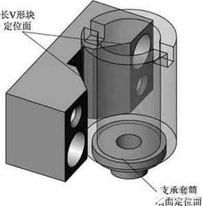
Positioning plan and positioning components
Determine the positioning plan and select positioning components:
Positioning scheme and positioning elements for aluminum thin sleeve parts
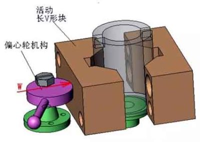
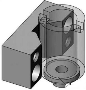
Clamping plan and clamping device design
▲Clamping mechanism
Design a fixture scheme for aluminum thin sleeve parts
▲Guide and automatic release device in the clamping mechanism
Design of parts fixture structure
1. Parts positioning device
The long V-shaped block is the main positioning element in the fixture, eliminating 4 uncertainties of the workpiece. It can be found in relevant national standards or industry standards.
Support sleeve:
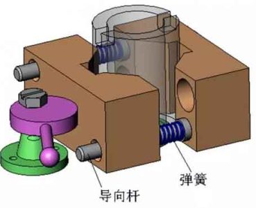
Guide and automatic release device in CNC fixture mechanism
2. Parts clamping device
Dispositivo de posicionamiento de accesorios
▲Eccentric wheel
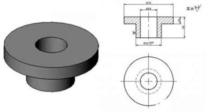
Support sleeve of fixture
▲Eccentric wheel bracket
3. assisting equipments
Fixture clamping device
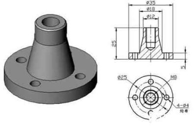
▲ Tool setting block of parts
4. Part clamping details
Soporte rueda excéntrica de abrazadera
5. General drawing of parts fixture
Tool setting block for CNC machining parts
1. Part clamping details
2. Cylindrical pin
3. Eccentric bracket
4. Eccentric
5. Movable V-shaped block
6. Tool setting block for parts
7. Fixed V-shaped block
Part. 2, Process plan for inner hole machining of aluminum alloy thin-walled parts
The workpiece is processed by seamless steel pipe. The surface roughness of the inner hole and the outer wall is Ra1.6μm, which can be achieved by turning, but the cylindricity of the inner hole is 0.03mm, which requires higher requirements for thin-walled parts. En producción en masa, the process route is roughly:
Material blanking — heat treatment — turning the end face — turning the outer circle — turning the inner hole — quality inspection.
The process of “processing the inner hole of the workpiece” is the key to quality control. We put aside the outer circle and thin-walled casing, it is difficult to guarantee a 0.03mm cylinder when the inner hole is cut.
The key technology of turning holes
The key technology of turning holes is to solve the rigidity and chip removal problems of the inner hole turning tool. To increase the rigidity of the inner hole turning tool, take the following measures:
1. Try to increase the cross-sectional area of the tool holder, usually the tip of the inner hole turning tool is located above the tool holder. De este modo, the cross-sectional area of the tool holder is less, menos que 1/4 of the cross-sectional area of the hole, as shown in the left figure below. If the tip of the inner hole turning tool is located on the center line of the tool holder, the cross-sectional area of the tool holder in the hole can be greatly increased, as shown in the right figure below.
2. The extension length of the tool holder can be 5-8mm longer than the length of the workpiece to increase the rigidity of the turning tool holder and reduce the vibration during the cutting process.
Solve chip evacuation problems
Mainly control the outflow direction of cutting chips. Rough turning tools require chips to flow to the surface to be machined (front chip removal). To this end, the inner hole turning tool with a positive edge inclination angle is used, as shown in the figure below.
In fine turning, the chip flow direction is required to be forward chip removal (hole core chip removal). Por lo tanto, pay attention to the grinding direction of the cutting edge when sharpening the knife edge, and use the chip removal method that is inclined to the front edge. As shown in the figure below, the alloy used for fine turning tools is YA6. The current M type has better bending strength, wear resistance, impact toughness, and resistance to steel and temperature.
When sharpening, el ángulo de inclinación está redondeado con un ángulo en forma de arco de 10-15°, El ángulo de relieve está a una distancia de 0,5-0,8 mm de la pared según el arco de mecanizado. (la línea inferior de la herramienta está a lo largo del arco), c La dirección k del ángulo del filo de corte es §0.5-1 está a lo largo del borde de la viruta, La escobilla del limpiaparabrisas del punto B es R1-1.5, Es apropiado pulir el ángulo auxiliar del respaldo a 7-8°, El punto A-A del borde interior de E se muele formando un círculo para descargar virutas..
Método de mecanizado
1. Se debe mecanizar un eje protector antes de mecanizar. El objetivo principal de la protección del eje.:
El orificio interior del manguito de pared delgada torneado tiene el tamaño original., Y los centros delantero y trasero están fijos para que procese el círculo exterior sin deformación., y mantener la calidad y precisión del círculo exterior. Por lo tanto, the processing of the shaft guard is a key link in the process of processing the thin-walled casing.
45﹟Carbon structure round steel for processing shaft guard blanks; Turning the end face, opening two B-shaped center holes, rough turning the outer circle, leaving a margin of 1mm. After heat treatment, tempering and shaping, and then fine turning, leaving a 0.2mm margin for grinding. Re-heat the crushed fire surface to a hardness of HRC50, and then grind it with a cylindrical grinder as shown in the figure below. After the accuracy meets the requirements, it is completed and ready for use.
2. In order to complete the processing of the workpiece at one time, the blank retains the clamping position and cutting margin.
3. Firstly, the rough embryo is heat-treated, quenched, tempered and shaped, with a hardness of HRC28-30 (hardness within the processing range).
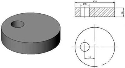
4. The turning tool adopts C620, and first put the front center into the spindle cone to fix it. To prevent deformation of the workpiece when clamping thin-walled sleeves, add an open-loop thick sleeve, as shown in the figure below.
In order to maintain mass production, one end of the outer circle of the thin-walled casing is processed to a uniform size d, and the ruler of t is the axial clamping position. The thin-walled casing is clamped and compressed to improve the quality of turning the inner hole and maintain the size. Considering that cutting heat is generated, the expansion size of the workpiece is difficult to grasp. It is necessary to pour sufficient cutting fluid to reduce the thermal deformation of the workpiece.
5. Clamp the workpiece firmly with an automatic centering three-jaw chuck, turn the end face, and rough turn the inner circle. Leave a margin of 0.1-0.2mm for fine turning, and replace it with a fine turning tool to process the cutting margin until the guard shaft meets the requirements of excessive fit and roughness. Remove the inner hole turning tool, insert the guard shaft to the front center, use the tailstock center to clamp according to the length requirement, change the external turning tool, and rough turn the external circle. Finalmente, the precision turning parts meet the drawing requirements. After passing the inspection, use a cutting knife to cut according to the required length. In order to make the cut smooth when the workpiece is disconnected, El borde del cuchillo debe estar inclinado para que la cara final de la pieza de trabajo quede suave.; La pequeña parte del eje del protector está rectificada para cortar el espacio que queda.. El eje protector sirve para reducir la deformación de la pieza de trabajo., prevenir la vibración, y caer y chocar al cortar.
El método anterior para procesar carcasas de paredes delgadas resuelve el problema de la deformación o de causar errores de tamaño y forma al no cumplir con los requisitos.. La práctica ha demostrado que la eficiencia del procesamiento es alta., fácil de operar, y adecuado para el procesamiento de piezas largas y de paredes delgadas, el tamaño es fácil de entender, la segunda finalización, Y la producción en masa es más práctica..