 English
 العربية
 中文(漢字)
 Čeština
 Dansk
Dansk Nederlands
 Suomi
Suomi Français
 Deutsch
 Italiano
 日本語
日本語 ಕನ್ನಡ
ಕನ್ನಡ 한국어
한국어 Português
 Русский
 Slovenčina
 Español
 Svenska
 Türkçe
Aparecen contornos complejos en la fabricación de herramientas y moldes., y son productos producidos en masa. Antes de la aparición de las máquinas herramienta CNC, Los troqueles de forja y los troqueles utilizados en la industria automotriz se fabricaban principalmente a mano.. Después de la década de 1970, Las máquinas herramienta CNC se han utilizado ampliamente en la fabricación de herramientas y moldes.. Los contornos básicos de perfiles complejos normalmente se procesan mediante fresado., y las máquinas herramienta CNC circundantes se configuran inicialmente con un varillaje de tres ejes.
After entering the 1980s, five-axis milling machines have been widely used in complex surface processing. The contour of the workpiece after milling is very close to the final shape of the workpiece, but the last finishing process is still manual. In the late 1980s, high-speed cutting technology gradually developed and matured, and its application in industrial production has been continuously improved in terms of machine tools, cutting tools and other related technologies. Since high-speed cutting can double the feed speed, the feed pitch can be reduced without reducing production efficiency. This provides a prerequisite for improving the shape accuracy of the workpiece and reducing the surface roughness. Actualmente, most of the workpieces processed by high-speed milling no longer need the last manual processing procedure, but can be directly put into use.
5-mecanizado por ejes de perfiles complejos
New tool materials: such as alumina-based ceramics, silicon nitride-based ceramics, cermets, carburo cementado, especially the continuous development of superhard coatings, making hard face milling possible. The mold surface can be milled to shape after quenching, thereby avoiding deformation caused by quenching after milling. This not only simplifies the machining process, but also improves the accuracy of the workpiece.
Además, with the application of precision forging in die manufacturing, the die blank after forging already has its designed basic shape, and the remaining machining allowance is insignificant compared with the milling of the entire blank. In this case, in addition to milling, it can also be processed by high-efficiency grinding. Compared with hard face milling, high-efficiency grinding can not only improve the shape accuracy of the workpiece, but also improve the surface roughness of the workpiece. There are many high-efficiency grinding methods, usually high-speed grinding with spherical grinding wheels and belt grinding with small-diameter belt wheels.
Type of milling cutter
Three-dimensional free-form surfaces in tools and molds are usually processed on a 5-axis machining center. Since the material of the workpiece is mostly alloy steel or tool steel, the structure of the machine tool and the numerical control system must consider the requirements of productivity and workpiece accuracy in the processing process, and make appropriate layout and optimization based on this. In order to ensure that the machine tool does not undergo too much deformation when cutting various mold materials, the machine tool stiffness should be the first priority when determining the machine layout. Larger axis machining center, most of a gantry structure, some small-sized five-axis machining center is also sometimes used high column structure.
Since the beginning of the 1990s, almost all complex shapes have been processed by high-speed cutting in production. El objetivo es mejorar la eficiencia de la producción., reducir el costo del producto, y al mismo tiempo mejorar la precisión de la forma de la pieza de trabajo y reducir la rugosidad de la superficie. In order to meet the needs of high-speed cutting, el husillo de la máquina herramienta casi sin excepción utiliza un husillo eléctrico. La velocidad del husillo es continuamente variable según el diámetro de la herramienta utilizada., and the speed ranges from several thousand revolutions per minute to tens of thousands of revolutions per minute. The drive system of the sliding table is also different from conventional machining centers in high-speed cutting. Commonly used system with high-speed drive nut screw assembly and linear motor drive, a maximum feed speed can reach 100m / min or more.
The appearance drawing of CNC machining complex cavity surface
When processing complex surfaces, El sistema CNC de la máquina herramienta también debe cumplir algunos requisitos especiales.. Por ejemplo, CNC machining programs for complex surfaces are generally generated on CAD/CAM software. A profiled program often requires several megabytes (Byte) de espacio de almacenamiento, and it is no longer possible to transfer NC programs with a floppy disk. Por lo tanto, the CNC system must have the function of networking with other computer systems in order to receive the CNC program directly from the CAD/CAM. Además, El sistema de control numérico también debe adoptar tecnología de control avanzada., en primer lugar, it requires the function of LookAhead. En otras palabras, antes de que la máquina herramienta procese una determinada pista, El sistema de datos analiza previamente la superficie a procesar.. According to the curvature of each point of the curved surface and the connection relationship of each adjacent point, the feed speed of the machine tool is appropriately adjusted to achieve the highest productivity under the premise of ensuring the accuracy of the workpiece. In order to reduce dynamic errors during processing, the new servo error correcting data using a conventional tandem system is no longer proportional integral derivative (PID) controller, instead of using the state regulator by compensating for the position and speed state parameters. Using this kind of regulator can completely eliminate the drive hysteresis error, Compensar el error no lineal causado por el espacio o la fricción., e incluso compensar ciertas vibraciones de la máquina herramienta. Para cumplir con los requisitos de mejorar la precisión de la forma de la pieza de trabajo y reducir la rugosidad de la superficie..
Setting of the cutting path of the cavity surface
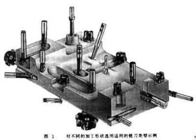
The tool system plays a decisive role in the production efficiency and processing quality when processing complex profiles. Al seleccionar un sistema de herramientas de corte, we must first start from the geometry of the parts to be processed, and reasonably use the types of cutting tools. Como se muestra en la figura 1, the geometry of each part is very different. If only a ball-end milling cutter is used for processing, a ball-end milling cutter with a small diameter must be selected, which makes it difficult to improve processing efficiency. Además, the arc radius of some parts is so small that it cannot be processed even with a small ball end mill. Por lo tanto, taking into account the requirements of both production efficiency and workpiece shape, other types of milling cutters must be equipped on the five-axis machining center for processing complex profiles, such as end mills and three-face milling cutters.
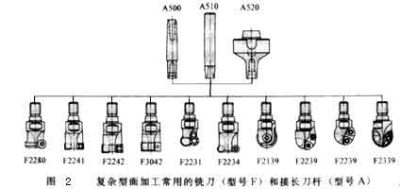
Cifra 2 shows some types of milling cutters. Siempre que el tamaño lo permita, regardless of the shape of the tool, the cutting edge should be a milling insert with a convertible clamp. Such knives can be combined in a variety of ways because of the blade and the body, and the blade and the body can be produced by different companies. Por lo tanto, large-scale specialized production can be formed, which not only helps to improve the quality of the tool, but also helps to reduce the production cost of the tool.
Actualmente, most of the indexable blades on the market use CVD coated carbide blades. In order to achieve higher pseudo-abrasion resistance, the indexable inserts are all multi-layered coatings. Bizhi Al2O3 can improve the chemical stability of the blade. TiN and TiCN can enhance the wear resistance of the blade. In order to enhance the sharpness of the blade, in addition to the low-temperature CVD method, the coating can also be produced by the PVD method. Some processing has very strict requirements on the blade. The blade must have a sharp cutting edge to reduce the roughness of the finished surface, but also have a high wear resistance to ensure the shape accuracy of the workpiece. In this case, a combination of multiple coatings must be used. In order to ensure that the use of some blades is foolproof, the number of coating layers can be as high as 100.
The life of the tool is closely related to the feed rate, cutting speed and depth of cut. The optimal cutting amount is often a small range, que debe determinarse de acuerdo con la herramienta específica y el material de la pieza de trabajo.
Además, estrategias de corte como: The planning of the tool path, the normal vector of the tool axis surface (the normal direction of the surface at this point) or the different methods along the surface tangent vector (the tangent direction of the surface at this point), etc., are also a key factor for processing complex surfaces . No sólo afecta a la rugosidad de la superficie de la pieza procesada., pero también afecta la forma y la precisión dimensional de la pieza de trabajo.. Cifra 3 shows the different cutting strategies used when machining a cylindrical surface. For cutting in the circumferential direction, the tool path needs to be interpolated in two-axis linkage. Al cortar a lo largo de la dirección generatriz, la herramienta solo necesita realizar una interpolación de un solo eje. Además, Los diferentes métodos de corte tienen grandes diferencias en el desgaste de la herramienta.. The tool wear during down milling is significantly lower than that of up milling, y el desgaste durante el fresado alternativo es mucho mayor que el del fresado unidireccional.
Para mejorar la estabilidad del proceso de mecanizado., when optimizing the cutting strategy, the continuity of the cutting must be ensured, and the cutting motion and idle stroke must be reduced as much as possible in order to shorten the cutting time. When the rough milling of steel, must ensure continuous climb milling, to minimize the peak of the cutting blade during cutting of the amount of fluctuation.
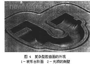
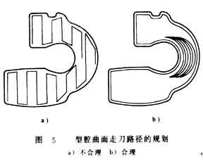
Al procesar la pieza de trabajo que se muestra en la Figura 4, if the row cut trajectory section processing shown in Figure 5a is used; El movimiento de la herramienta es muy irrazonable., las condiciones de corte son muy insatisfactorias, the processing time is 33min, y la rugosidad de la superficie de la pieza de trabajo es de 6-9 μm. If you switch to the circle-cutting path shown in Figure 5b for processing, el tiempo de procesamiento es aproximadamente 27 minutos. Al mismo tiempo, the roughness of the workpiece can also be reduced to 2 ~ 4μm.