 English
 العربية
 中文(漢字)
 Čeština
 Dansk
Dansk Nederlands
 Suomi
Suomi Français
 Deutsch
 Italiano
 日本語
日本語 ಕನ್ನಡ
ಕನ್ನಡ 한국어
한국어 Português
 Русский
 Slovenčina
 Español
 Svenska
 Türkçe
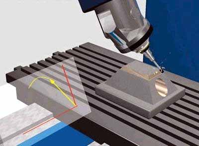
Mit der Zunahme des Designs von facettenreichen und komplex gebogenen Teilen, 5-Die Achsbearbeitung wird einen zunehmenden Anteil der CNC-Bearbeitung ausmachen. Weil die 5-Achsen-CNC-Bearbeitung zwei Rotationsfreiheitsgrade hinzufügt, Dies erhöht die Schwierigkeit der Berechnung der CNC-Bearbeitungsbewegungssimulation und der Überprüfung von Werkzeuginterferenzen, insbesondere bei der Bearbeitung von Teilen mit extrem komplexen Formen. daher, um sicherzustellen, dass 5-Achsen-CNC-Werkzeugmaschinen eine hocheffiziente und qualitativ hochwertige Fräsbearbeitung durchführen, Die Entwicklung von Software zur 5-Achsen-Werkzeugweggenerierung und Interferenzprüfung wird zu einem wichtigen Thema werden.
Die Feature-Projektionsmethode eignet sich für die Interferenzverarbeitung von 5-Achsen-CNC-Bearbeitungswerkzeugen, das ist, the machining surface is discretized into a series of surface feature points. Whether the tool interference occurs can be judged by whether the feature point enters the inside of the tool surface. Gleichzeitig, the machining surface and the tool surface are projected onto a specific plane, and only the feature detection points in the curved surface area of the enveloping tool projection graph are checked for interference, which improves the efficiency of interference detection.
Verhindern Sie Werkzeuginterferenzen beim 5-Achsen-Fräsen
1. Inspection method for tool interference
Coordinate system and coordinate transformation
Wie in der Abbildung gezeigt 1, the local coordinate system L of 5-axis circular cutter milling is represented as XL axis, YL axis and ZL axis. The YL axis always points to the cutting direction f of the tool contact (referred to as CC point) OL. The ZL axis points to the normal direction n of the surface, and the XL axis is determined by the right-hand rule of the YL axis and the ZL axis. The tool generally rotates around the XL axis from the ZL axis to the YL axis by a lead angle (heel angle) A, and rotates around the ZL axis one by one side slip angle b. Zusätzlich, the tool coordinate system T (XT, YT, ZT) can also be defined at the tool location point (CL point for short) OT. The YT axis points to the direction of the line connecting the CL point and the CC point. The ZT axis is the tool axis vector direction, and the XT axis is the direction determined by the right-hand rule of the YT axis and the ZT axis. The coordinate origin is located at the tool center point (ie CL point) OT. In order to simplify the interference check, the tool surface with a relatively regular shape is used as the reference for interference check. The machined surface is discretized to express the shape of the surface in the form of a set of characteristic points. The original data of these feature points are expressed in the world coordinate system W, so the feature point data must first be transformed from the world coordinate system W (OW-XW, YW, ZW) to the local coordinate system L (OL-XL, YL, ZL) ). It is then transformed from the local coordinate system L to the tool coordinate system T (OT-XT, YT, ZT).
Interference check method
If the tool and power head have been selected, the size of the tool system (tool and power head) is known. Whether the tool system interferes with the machined surface can be determined by judging whether the characteristic point P enters the inside of the tool surface. Wie in der Abbildung gezeigt 2, it is the positional relationship between the tool system and the machined surface when the ring knife is processed. In the tool coordinate system, let the coordinate of the characteristic point P be PI (Xpt, Ypt, Zpt). According to the different combination parts of the tool system, the coordinate value Zpt of the characteristic point P is divided into 4 sections for judgment. Details are as follows:
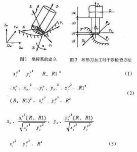
5-axis milling stroke setting formula
When the feature point P is within the range of u1, no interference will occur.
When the characteristic point P is in the range of u2, there are two situations, and the torus is divided into two parts:
Der kleine zylindrische Teil P1 und der kreisförmige Ringteil P2. Wenn der Merkmalspunkt am zylindrischen Teil P1 beteiligt ist, Es kommt zu Werkzeuginterferenzen, das ist, es ist zufrieden
wobei R den Radius des Werkzeugs darstellt, und R1 stellt den Radius des Rings des kreisförmigen Werkzeugs dar.
Wenn der Merkmalspunkt am Ringteil P2 beteiligt ist, Es kommt auch zu Werkzeuginterferenzen, das ist, es ist zufrieden
im Stil
Wenn der Merkmalspunkt P nicht in die Teile P1 und P2 eindringt, Es treten keine Werkzeugbeeinträchtigungen auf.
Wenn der charakteristische Punkt P im Bereich von u3 liegt, wenn der Abstand zwischen dem charakteristischen Punkt P und der ZT-Achse kleiner als der Werkzeugradius ist, Es kommt zu Werkzeuginterferenzen, was zufrieden ist
Ansonsten, Es treten keine Werkzeugbeeinträchtigungen auf.
Wenn der charakteristische Punkt P im Bereich von u4 liegt, die Situation ist die gleiche wie die von 3, solange der Werkzeugradius R in der Formel angegeben ist (3) wird zur Beurteilung durch den Kraftkopfradius d/2 ersetzt.