In einem Augenblick, Ich betreibe seit mehr als zehn Jahren CNC-Drehmaschinen, und haben einige Bearbeitungskenntnisse und Erfahrung mit CNC-Drehmaschinen gesammelt. Einschließlich Drehen verschiedener Materialien (Edelstahl, Aluminium, Kupfer-Kohlenstoffstahl, Titan, Hartmetall, usw.). Aufgrund des häufigen Austauschs verarbeiteter Teile und begrenzter Werksbedingungen, Seit zehn Jahren programmieren wir selbst, Einstellwerkzeuge selbst, Debuggen und Fertigstellen der Teilebearbeitung selbst. Zusammenfassend, Die Bedienfähigkeiten sind in die folgenden Punkte unterteilt.
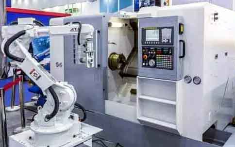
Operating CNC lathe
Eins, Programming skills of lathe
Because our factory has high requirements for the accuracy of processed products, the things that need to be considered when programming are:
1. Processing sequence of parts:
Drill first, then turn the flat end (this is to prevent shrinkage during drilling);
Rough turning first, then fine turning (this is to ensure the accuracy of parts);
The position with large tolerance is processed first, and the final processing with small tolerance (this is to ensure that the surface of small tolerance size is not scratched and prevent deformation of parts).
2. Choose reasonable speed, feed and depth of cut according to material hardness:
1) Select carbon steel material with high speed, high feed rate and large cutting depth. Wie zum Beispiel: 1Gr11, select S1600, F0.2, and cut depth 2mm;
2) Low speed, low feed rate and small cutting depth are selected for hard alloy. Wie zum Beispiel: GH4033, select S800, F0.08, and cut depth 0.5mm;
3) Choose low speed, high feed rate and small cutting depth for titanium alloy. Wie zum Beispiel: Ti6, select S400, F0.2, and cut depth 0.3mm.
Take the processing of a certain part as an example: the material is K414, which is a very hard material. After many tests, the final selection is S360, F0.1, and the depth of cut 0.2, in order to process qualified parts.
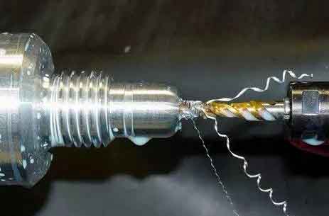
CNC-Drehbohrprozess
two, Tool setting skills of lathe
Tool setting is divided into: tool setting with tool setting instrument and direct tool setting. The tool setting technique mentioned below is direct tool setting.
First select the center of the right end face of the part as the tool setting point and set it as the zero point. After the machine tool returns to the origin, each tool that needs to be used is set with the center of the right end face of the part as the zero point;
When the tool touches the right end face, enter Z0 and click to measure, and the measured value will be automatically recorded in the tool compensation value, which means that the Z-axis tool is set. X tool setting is a trial cutting tool setting, and the outer circle of the part is turned with a tool. Measure the value of the turned outer circle (Zum Beispiel, x is 20mm) and enter x20, click Measure, the tool compensation value will automatically record the measured value, and then the x axis will also complete the tool setting;
This tool setting method will not change the tool setting value even after the machine is powered off. It is suitable for mass production of the same part for a long time, during which the lathe does not need to recalibrate the tool after restarting.
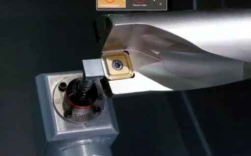
Common tool setting instruments for CNC lathes
three, Debugging skills of lathe
After the parts are programmed, test cutting and debugging are required after the tool is adjusted. In order to prevent errors and tool setting errors in the program from causing collision accidents, we should first perform idle stroke simulation processing. In the coordinate system of the machine tool, move the tool to the right by 2-3 times the total length of the part; Then start simulation processing. After the simulation processing is completed, confirm that the program and tool setting are correct, and then start processing the parts. After the completion of the first pieces of machining parts, the first self-test, to confirm eligibility, check to find full-time inspectors, qualified full-time inspectors confirmed this indicates the end of commissioning.

Trial cutting and debugging of CNC lathe
four, Finish machining of parts
After the trial cut of the first prototype is completed, the parts will be mass produced. Jedoch, the qualified product of the prototype does not mean that the entire batch of parts will be qualified, because in the processing process, the tool will wear out due to the difference in the processing materials. When the processing material is soft, the tool wear is small, and the processing material is hard and the tool wears quickly. daher, in the process of processing, it is necessary to check more, increase and decrease the tool compensation value in time to ensure the qualified parts.
Take a part as an example, the processing material is K414, and the total processing length is 180mm. Due to the extremely hard material, the tool wears very quickly during processing. From the start point to the end point, an angle of 10-20mm will be generated due to tool wear. daher, we must artificially add a compensation value of 10-20mm in the program, so as to ensure the qualified parts.
The basic principles of lathe processing: Rough machining first, remove excess material from the workpiece, and then finish machining; Avoid vibration during processing; Avoid the thermal denaturation of the workpiece during processing. There are many reasons for the vibration caused by the excessive load; It may be the resonance of the machine tool and the workpiece, or the rigidity of the machine tool may be insufficient, or it may be caused by the passivation of the tool. We can reduce vibration by the following methods; Reduce the transverse feed and processing depth, check whether the workpiece is clamped securely, increase the speed of the tool and reduce the speed to reduce the resonance. Zusätzlich, check whether it is necessary to replace a new tool.
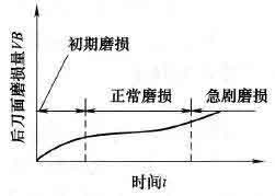
Turning tool wear process and blunt standard
Fives, The experience of preventing machine collision
Machine tool collision is a great damage to the accuracy of the machine tool, and it has different effects on different types of machine tools. Allgemein gesagt, it has a greater impact on machine tools with low rigidity. daher, for high-precision CNC lathes, collisions must be absolutely eliminated. As long as the operator is careful and masters certain anti-collision methods, collisions can be prevented and avoided.
The main reason for the collision:
1> Enter the diameter and length of the tool incorrectly;
2> The size of the workpiece and other related geometric dimensions are entered incorrectly, and the initial position of the workpiece is incorrectly positioned;
3> The workpiece coordinate system of the machine tool is set incorrectly, or the zero point of the machine tool is reset during the machining process, which causes a change. Most of the machine tool collisions occur during the rapid movement of the machine tool. The collisions that occur at this time are also the most harmful and should be absolutely avoided. daher, the operator must pay special attention to the machine tool in the initial stage of executing the program and when the machine tool is changing tools. Zu diesem Zeitpunkt, once the program is edited incorrectly and the diameter and length of the tool are entered incorrectly, collisions are likely to occur. At the end of the program, if the NC axis retracts the tool in a wrong sequence, then collisions may also occur.
In order to avoid the collision mentioned above, the operator must give full play to the sensory functions when operating the machine tool. Observe whether there is abnormal movement of the machine tool, whether there is spark, whether there is noise and abnormal noise, whether there is vibration, whether there is a burning smell. The program should be stopped immediately when the abnormal situation is found, and the machine tool can continue to work after the problem of the standby bed is solved.
 English
 العربية
 中文(漢字)
 Čeština
 Dansk
Dansk Nederlands
 Suomi
Suomi Français
 Deutsch
 Italiano
 日本語
日本語 ಕನ್ನಡ
ಕನ್ನಡ 한국어
한국어 Português
 Русский
 Slovenčina
 Español
 Svenska
 Türkçe

