 English
 العربية
 中文(漢字)
 Čeština
 Dansk
Dansk Nederlands
 Suomi
Suomi Français
 Deutsch
 Italiano
 日本語
日本語 ಕನ್ನಡ
ಕನ್ನಡ 한국어
한국어 Português
 Русский
 Slovenčina
 Español
 Svenska
 Türkçe
FOR EVERY PURPOSE
Aluminium verarbeiten, Edelstahl, Titan, Kunststoff und vieles mehr mit der CNC-Portalfräsmaschine. Mit unserem computergesteuerten Fräsen können Sie präzise produzieren, genau und zuverlässig. Ob für die Werkstatt (Hobby, Modellbau, Hersteller), der Handel (CNC-Produktion, Prototypenbau, Serienfertigung). Bei uns finden Sie die passenden Frästeile für Ihre Anwendung.
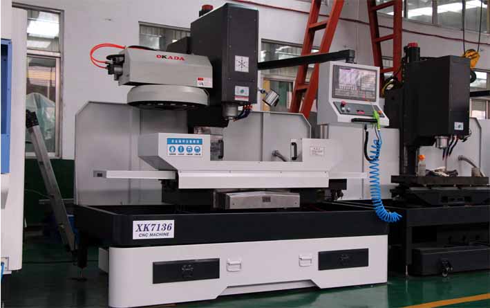
CNC-Fräsmaschine
The introduction of computerized numerical control (CNC) has exponentially expanded applications of industrial machines by programmable automation of production and achieving impossible movements performed manually. such as circles, diagonal lines and other figures complicated that enable the manufacture of parts with highly complex profiles. This also translates into the optimization of many essential variables of any manufacturing process: productivity, precision, safety, speed, repeatability, flexibility and reduction of waste.
The multiplicity of milling machines that exist today has comfortably expanded into the proliferation of their CNC-equipped peers. Tatsächlich, there are also special kits to transform old milling machines into a CNC milling machine.
Grundsätzlich, the CNC milling machines are very similar to the conventional ones and have the same moving parts, das ist, the table, the cutting head, the spindle and the side and cross slide carriages. Jedoch, they do not have levers or cranks to operate these moving parts, but rather a screen inserted in a panel full of controls and a metal box that houses the electrical and electronic components that regulate the operation of motors destined to carry out the same work that they did. the levers and cranks of the old machines. Among these components is the CNC, which is a computer mainly responsible for the movements of the milling machine through the corresponding software. The combination of electronics and drive motors or servo motors is capable of achieving all possible milling operations.
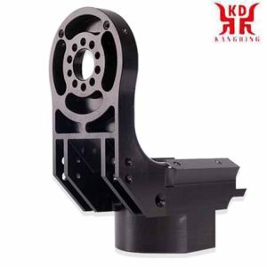
CNC-Bearbeitung einer Portalfräsmaschine
To understand the movement control exercised by the CNC, we are going to briefly review how a conventional milling machine works.
The figure schematizes a typical milling machine. In this type of machine, the cranks actuate the moving parts manually so that the cutting tool (milling cutter) moves linearly in at least three axes, which are called main axes:
X axis: horizontal and parallel to the clamping surface of the part. It is associated with the movement in the longitudinal horizontal plane of the milling table.
und Achse: forms a direct direction trihedron with the X and Z axes. It is associated with the movement in the horizontal transverse plane of the milling table.
Z axis: where the cutter is mounted, it is the one that has the cutting power and can adopt different positions according to the possibilities of the head. It is associated with the vertical displacement of the machine head.
If the milling machine has a fixed table, these three movements are executed by the spindle.
Jedoch, Es ist klar, dass das Fräsen komplexerer Teile eine größere Anzahl von Achsen erfordert, deren Bewegungsbahn nicht nur linear ist, aber auch rotierend. An diesem Punkt kommt das Konzept der CNC ins Spiel, Dadurch entsteht eine Vielzahl komplementärer Achsen, die unabhängig voneinander gesteuert und durch die Bewegung von Drehtischen bestimmt werden / oder verstellbare Köpfe. Dadurch entstehen unterschiedliche Maschinenmodelle, die die Bearbeitung des Teils in unterschiedlichen Ebenen und Anstellwinkeln ermöglichen.
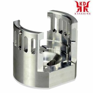
CNC machining cavity of milling machine
In der folgenden Abbildung sehen wir ein Beispiel einer CNC-Fräsmaschine mit ihren Grundkomponenten und Hauptkomponenten (X, Y, Z) und ergänzend (B, W) Achsen.
1 – Spalte
2 – Werkstück
3 – Frästisch, mit Bewegung in der X- und Y-Achse
4 – Strawberry
5 – Schneidkopf inklusive Spindelmotor
6 – CNC-Bedienfeld
7 – Kühlmittelschläuche
X, Y, Z – Main axes of displacement
B – Complementary axis of rotary displacement of the cutting head
W – Complementary axis of longitudinal displacement of the cutting head
The main function of the CNC is to control the movements of the table, the transverse and longitudinal carriages and / or the spindle along their respective axes by means of numerical data. Jedoch, this is not all, because the control of these movements to achieve the desired final result requires the perfect adjustment and the correct synchronization between different devices and systems that are part of every CNC process. These include the main and complementary axes, the transmission system, the workpiece clamping systems and the tool changers, each of which presents its modalities and variables that must also be properly stipulated.
This rigorous control is carried out by software that is supplied with the milling machine and is based on one of the CNC numerical programming languages, such as ISO, HEIDENHAIN, Fagor, Fanuc, SINUMERIK and Siemens. This software contains numbers, letters and other symbols – Zum Beispiel, the G and M codes – that are encoded in an appropriate format to define an instruction program capable of carrying out a specific task. G codes are machine motion functions (rapid moves, Einspeisungen, radial feeds, pauses, cycles), while M codes are miscellaneous functions that are required for machining parts, but are not machine motion. (spindle start and stop, Werkzeugwechsel, coolant, program stop, usw.). From this it follows that to operate and program this type of machine requires basic knowledge in machining operations on conventional equipment, elementary knowledge of mathematics, technical drawing and handling of measuring instruments.
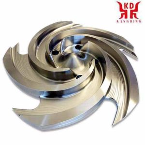
Fräslaufradbearbeitung der Fräsmaschine
Currently the use of CAD (computer-aided design) and CAM (computer-aided manufacturing) programs is an almost mandatory complement to any CNC machine, therefore. Allgemein, the manufacture of a part involves the combination of three types of software:
CAD: makes the design of the part.
CAM: calculates the displacements of the axes for the machining of the part and adds the feed rates, rotation speeds and different cutting tools.
Control software (included with the machine): receives the instructions from the CAM and executes the orders to move the moving parts of the milling machine in accordance with these instructions.
The following video illustrates the manufacture of a part using CAD / CAM:
CNC milling machines are specially adapted for milling profiles, cavities, surface contours and die cutting operations, in which two or three axes of the milling table must be controlled simultaneously. Although, depending on the complexity of the machine and the programming carried out, CNC milling machines can operate automatically, an operator is usually required to change the cutters, as well as to mount and dismount the workpieces.
Industries that routinely use CNC milling machines include automotive (design of engine blocks, Formen, and miscellaneous components), Luft- und Raumfahrt (aircraft turbines), and electronics (mold and prototyping), as well as manufacturing of machinery, instruments and electrical components.
Let’s see in this video some types of CNC milling machines, as well as working examples.