 English
 العربية
 中文(漢字)
 Čeština
 Dansk
Dansk Nederlands
 Suomi
Suomi Français
 Deutsch
 Italiano
 日本語
日本語 ಕನ್ನಡ
ಕನ್ನಡ 한국어
한국어 Português
 Русский
 Slovenčina
 Español
 Svenska
 Türkçe
Broaching of aluminum alloy, Edelstahl, copper and titanium alloy parts:
Broaching is a highly efficient finishing method. In addition to broaching round holes, it can also broach through holes and internal keyways of various cross-sectional shapes, wie in der Abbildung gezeigt 7-19. The achievable dimensional tolerance grade for broaching round holes is IT9~IT7, and the surface roughness value is Ra1.6~0.4μm.
1. Broaching can be regarded as planing with multiple planers arranged in order of high and low, wie in der Abbildung gezeigt 7-20. The structure of the round hole broach is shown in Figure 7-21, and the functions of each part are as follows:
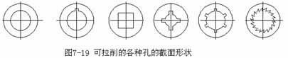
Several different broaching hole shapes
The shank of the broach: It is the part where the broach is clamped by the knife clamp of the broach.
The neck diameter of the broach is the smallest: when the broaching force is too large, it generally breaks here, which is convenient for welding repair.
The transition cone of the broach: guide the broach into the hole being machined.
The leading part of the broach: to ensure a smooth transition of the workpiece to the cutting part, und gleichzeitig, check whether the aperture before pulling is too small to prevent the first tooth from being damaged due to excessive load.
The cutting part of the broach: including rough cutting and fine cutting, it undertakes the main cutting work.
The leading part of the broaching knife. When the broaching cutter teeth cut away from the workpiece, it prevents the workpiece from sagging, scratching the machined surface and damaging the cutter teeth.
Method of broaching round holes
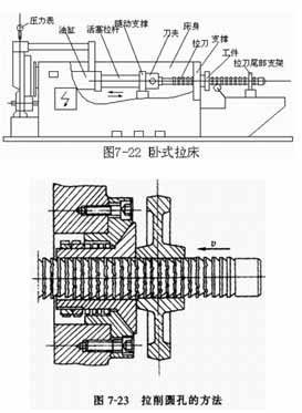
The horizontal broaching machine is shown in Figure 7-22. The machine body is equipped with a hydraulic drive cylinder, and the right end of the piston rod is equipped with a follower bracket and a knife holder to support and clamp the broaching knife. Before work, the broaching knife is supported on the roller and the tail bracket of the broach, and the workpiece is penetrated by the left end of the broach. When the tool holder clamps the broaching knife to move linearly to the left, the workpiece rests on the “support”, and the broaching knife can complete the cutting process. The linear movement of the broaching knife is the main movement, and the feed movement is completed by the lifting of each tooth of the broaching knife.
Method of broaching internal groove
(1) Das Räumen runder Löcher ist in der Abbildung dargestellt 7-23. Der Räumlochdurchmesser beträgt im Allgemeinen 8 bis 125 mm, und das Verhältnis von Länge zu Durchmesser des Lochs beträgt im Allgemeinen nicht mehr als 5. Allgemein, Eine präzise Vorbearbeitung vor dem Räumen ist nicht erforderlich, und das Räumen kann nach dem Bohren oder Vorbohren erfolgen. Wenn die Stirnfläche des Werkstücks nicht senkrecht zur Lochachse steht, die Stirnfläche wird gegen die Kugelscheibe der Räummaschine gedrückt. Unter der Wirkung der Räumkraft, Das Werkstück und die Kugelscheibe werden leicht gedreht, sodass die Achse des Lochs automatisch in die gleiche Richtung wie die Achse der Räumnadel eingestellt wird, Dies kann verhindern, dass die Räumnadel bricht.
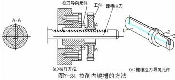
(2) Räumen der inneren Keilnut wie in Abbildung 7-24a gezeigt. Die Räumnadel mit Keilnut ist flach, mit Zähnen im oberen Teil. The correct position of the workpiece and the broaching knife is ensured by the guiding element. The cylinder 1 of the broaching knife guide element (Figure 7-24b) is inserted into the end hole of the broaching machine, the cylinder 2 is used to hold the workpiece, and the slot 3 is for the broaching knife.