 English
 العربية
 中文(漢字)
 Čeština
 Dansk
Dansk Nederlands
 Suomi
Suomi Français
 Deutsch
 Italiano
 日本語
日本語 ಕನ್ನಡ
ಕನ್ನಡ 한국어
한국어 Português
 Русский
 Slovenčina
 Español
 Svenska
 Türkçe
Hvad kan man gøre med en 5-akset fræser?
Det lyder måske mærkeligt, men hvis renæssancekunstneren havde byttet hammer og mejsel for en numerisk kontrol (CNC) og fræsemaskine, vi ville have tusindvis af statuer af David lavet af alle slags materialer i dag.
If you still have doubts that 5-axis milling is a real art form, please click here or here.
Whether you are sculpting a masterpiece out of marble or milling a blisk out of titanium – the basic principle is the same: You start off with a block of the material and remove the excess pieces until only the target object remains. Selvfølgelig, detaljerne i denne proces er meget mere komplicerede, især ved 5-akset fræsning.
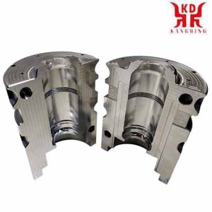
Anvendelser af 5-akset CNC fræsning
Hvad er 5-akset CNC fræsning?
Sagt enkelt, med 5-akset fræsning, et objekt eller fræseværktøjet flyttes samtidigt langs fem forskellige akser ved hjælp af en CNC-styring. Dette gør det muligt at bearbejde meget komplekse dele, derfor har 5-akset teknologi bevist sig særligt i flyindustrien.
Imidlertid, dette er ikke den eneste grund til, at 5-akset teknologi er blevet udbredt. Andre faktorer er:
1 , En tendens til behandling af objekter med enkelt opsætning (nogle gange omtalt som "færdig-i-en") at reducere gennemløbstiden og forbedre effektiviteten
2 , Muligheden for at forebygge arbejdsulykker ved at vippe fræseelementet eller fræsebordet på en kontrolleret måde, which also enables the process to be better coordinated with the geometry of the respective object
3 , The optimization of the tool life and the tool cycle as a side effect of the above-mentioned tilting function of the milling element or milling table by ensuring an optimal cutting position and a constant metal removal rate
Funktioner af 5-akset CNC fræsning
What about the axes in the 5-axis machining process?
We all know the story of Newton and the apple, but there is a story of the mathematician and philosopher René Descartes of similarly dubious origins.
Descartes was in bed (as mathematicians and philosophers do) when he noticed a fly buzzing through his room. He realized that he could describe the position of the fly in the three-dimensional space of the room with only three numbers, represented by the variables X, Y and Z.
This is the Cartesian coordinate system that is still in use today, more than three centuries after Descartes’ death. x, Y and Z therefore cover three of the five axes of the 5-axis machining process.
But what about the other two axes?
Imagine zooming in on Descartes ’fly in mid-flight. Instead of just describing their position as a point in three-dimensional space, we can also describe their orientation. When the fly changes direction, it does so in the same way as an airplane that tilts to maneuver. The fourth axis, EN, describes its lateral rotation around its own axis as an axis of rotation around X (called “rolling” in technical terms).
Following on from the aircraft comparison, the vertical inclination of the fly upwards or downwards is described by the fifth axis, B, as the axis of rotation around Y (called “nodding” in technical terms).
The careful reader will no doubt infer the existence of a sixth axis, C, rotating around the Z axis. In our example this is the horizontal rotation of the fly to the left or right (called “yaw” in technical terms).
If you have difficulty visualizing the six axes described above, the diagram below should serve as a guide:
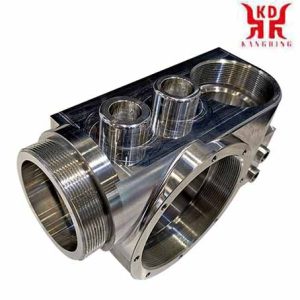
5-aksefræsning af maskinhus
The axes A, B and C are arranged alphabetically to match the axes X, Y and Z accordingly. Although there are 6-axis CNC machines such as For example, the portal milling machine Zimmermann FZ 100, 5-axis configurations are more common, as the sixth axis usually offers hardly any additional use.
A final note on the conventions of axis designations: In a vertical machining center, the X and Y axes correspond to the horizontal plane, while the Z axis corresponds to the vertical plane. In a horizontal machining center, the Z and Y axes are swapped. See the diagram below:
5-axis configurations
The specific configuration of a 5-axis milling machine determines which of the three axes of rotation it uses.
So z. B. a swivel table machine with the A-axis (rotating around the X-axis) and the C-axis (rotating around the Z-axis), while a swivel head machine with a B-axis (rotating around the Y-axis) and a C -Axis (rotating around the Z-axis) is working.
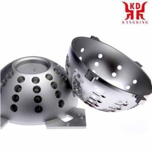
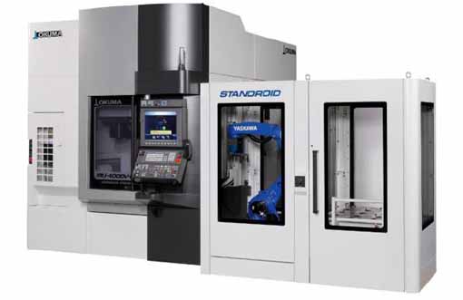
Inside view of the swivel table of the 5-axis, vertical machining center of the Okuma MU-4000V
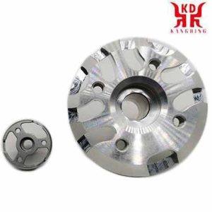
5-axis milled lampshade prototype
The axes of rotation in swivel table machines are operated by the movement of the table, while swivel head machines operate their axes of rotation by rotating a spindle. Both types have their own advantages. For eksempel, swivel table machines offer larger processing chambers because the swivel spindle does not require significant space. På den anden side, swivel head machines can also process heavier parts because the table is always horizontal.
How many axes are required?
You may have heard of machining centers with seven, nine, or even eleven axes. Although so many additional axes seem hard to imagine, the explanation for such staggering numbers is actually quite simple.
“When you are dealing with machines that e.g. For eksempel, having more than one turning spindle increases the number of axes, ”explained Mike Finn, Senior Engineer Industrial Applications at Mazak America.
“For example, we have machines with an additional, second spindle and lower turrets. With these machines you have several axes: the upper turret has 4 axes and the lower turret has 2 akser, then you have two opposing spindles that also have 2 akser. Such machines can have up to 9 akser, ”continued Finn.
“The parts you make are still 5-axis parts,” added Wade Anderson, product specialist and sales manager at Okuma America.
“A component such. B. a valve for the aerospace industry could easily be manufactured in our vertical machining center MU-5000, a 5-axis machine. We could also machine this part on a multi-axis machine with a B rotation axis and two spindles for two C axes each, plus the standard X, Y and Z axes. There is also the lower turret, which provides you with a second X and Z axis. So there are more machining axes available, but the part itself will have the same geometry, ”said Anderson.
So how many axes are really needed?
As is so often the case in manufacturing, the answer to this question depends on the particular application. Finn gave the following example:
“A turbine blade is a free-form surface and can be very complex. The most efficient method of machining such an object is 5-axis machining, in which the tool is guided in a spiral around the profile of the turbine blade. 3-axis machining is possible by fixing the blade in a certain position and then machining the surface along three linear axes, but this is usually not the most efficient method. ”
Anderson agreed: “Det afhænger af den respektive komponents geometri, om du har brug for en 3, 4 eller 5-akset konfiguration.”
Imidlertid, det er vigtigt at bemærke, at antallet af nødvendige akser afhænger af aspekter, der strækker sig ud over det objekt, der skal behandles direkte. Målet er hovedfaktoren, men det handler også om hver enkelt kundes langsigtede behov og mål, ”said Anderson.
“En kunde kunne vise mig en del, såsom et titanium beslag til rumfartsteknologi, og jeg kunne sige, "Dette er en perfekt del til et 5-akset bearbejdningscenter,’ men kunden planlægger måske allerede i fremtiden at lave dele, der kan bearbejdes bedre med en af vores MULTUS U-maskiner. Denne multifunktionsmaskine er måske ikke så optimalt egnet som et 5-akset bearbejdningscenter med hensyn til den aktuelle komponent, but it offers the customer the possibility of turning, shaft or chucker work that can also be applied to future components. ”
“Another aspect to consider is the dimensions of the processing chamber,” added Finn. “What are the maximum dimensions of an object that you can insert into the machine without affecting tool and position changes? It’s about understanding what is possible with the system and what is not. ”
5-axis machining vs. 3D udskrivning
What are the advantages of 5-axis machining?
Choosing between 3-axis machining and 5-axis machining is a bit like deciding between a MacDonald’s quarter pounder and a T-bone steak; If cost is your only concern, then the first option is clearly a better option.
Imidlertid, if you compare 5-axis machining with 3 + 2-aksebearbejdning, the decision is much more difficult.
5-axis vs 3 + 2-akse
In order to understand the subject, it is important to understand the difference between 5-axis machining and 3 + 2-aksebearbejdning. The former – also called continuous or simultaneous 5-axis machining, is accompanied by continuous adjustments to the alignment of the cutting tool along all five axes in order to keep the cutting nozzle optimally perpendicular to the workpiece.
Demo component made of 6010 aluminum produced on all 5 axes using a DMG MORI DMU50. Processing time: 13 minutter.
With the latter, on the other hand – also called 5-sided or 3 + 2-aksebearbejdning – a 3-axis program is executed in which the milling tool is fixed at an angle determined by the two axes of rotation. If the tool is realigned along the rotational axes between cuts, the process is called “5-axis indexed”; imidlertid, it is still one of the 3 + 2-axis machining processes.
3 + 2-axis demo component made of 6010 aluminium, produced on a DMG MORI DMU50. Processing time: 7 minutter.
The main advantage of 5-axis continuous machining over 5-axis indexed machining is speed, as the latter has to be stopped every time the tool is realigned, while the former does not.
I princippet, imidlertid, it is possible to achieve the same results with both variants. (Readers who disagree are welcome to share their examples of parts that can only be machined with continuous 5-axis technology in the comments section below the article.)
It should also be mentioned that the speed advantage is bought at the price of increased tool activity, which is associated with increased wear and tear and an increased need for crash detection. This is one of the reasons why continuous 5-axis machining is more of a challenge from an operational point of view.
5-axis machining vs. 3D udskrivning
3D printing or additive or generative manufacturing – is currently a hot topic in the production world, especially with regard to the comparison with subtractive manufacturing processes such as 5-axis machining.
Although it is sometimes suggested that these two methods are in competition with each other – especially by hardcore 3D fans who claim that the 3D – Technology will soon turn the entire manufacturing industry upside down -, From a more moderate point of view, additive and subtractive manufacturing processes appear rather than mutually complementary technologies.
“I don’t think additive manufacturing will completely take over the manufacturing landscape, but I think it offers opportunities to make parts that couldn’t have been made in the past,” said Finn. “There are still many parts that require subtractive machining. For example parts that have a very low roundness tolerance. ”
“It is possible to bring an element to a near net shape without any problems, but this element still has to be reworked in order to achieve sufficient tolerance,” added Finn.
Does that mean that the future of manufacturing lies in a hybrid production system consisting of 3D printing and 5-axis CNC – perhaps with a built-in coordinate measuring machine to check the dimensions?
Anderson was not sure: “The real application of 3D printing outside of a laboratory environment is not to have a combined system, but for example an LMD system (Laser Metal Deposition; tysk: laser metalaflejring) og samtidig en roterende eller fræsemaskine, der både gør det, de er bedst til, og kombinerer begge enheder med automatisering. ”
Pointen bag to separate systemer er bedre pulver- og spånstyring.
“Mængden af pulver, du skal bruge på et LMD-anlæg for at lave en 30-punds del, kan være hvor som helst fra 150-300 pund titanium,” sagde Anderson. “Når det sættes ind i en maskine, der kombinerer alle funktionerne, det er næsten umuligt at genvinde og genbruge pulveret.”
Med andre ord: 3D-print og 5-akset bearbejdning er mindre i konkurrence med hinanden, end de er komplementære til hinanden. "Jeg tror, at additiv fremstilling enormt kan reducere mængden af skrubbearbejdning involveret i fremstillingen,” slutter Finn.
Sådan får du mest muligt ud af 5-akset bearbejdning
Det er ikke ualmindeligt, at fordelene ved 5-akset teknologi ikke bliver brugt i tilstrækkeligt omfang.
Anderson agreed: “Det knuser hjertet i virksomheder som vores: Når vi ser en virksomhed, der går all-in ved køb af deres system og derefter kun bruger en brøkdel af funktionerne under idriftsættelsen af forskellige årsager, f.eks. bruger et multifunktionelt system med fem eller flere akser, såsom et 3-akset system. Sådan noget sker igen og igen. ”
"Ofte er dette fænomen relateret til virksomhedens HR-politik,” tilføjede Anderson. »Det handler om at træne og forstå, hvordan man bruger et system. Nogle gange er det svært for de ansvarlige at forestille sig, hvordan standardapplikationer kan varieres. F.eks. om den respektive del ikke også kunne bearbejdes med en øvre rotation, a lower rotation, a main spindle and a counter spindle at the same time in an integrated process. The possibilities may seem overwhelming to some and overwhelm them. ”
The importance of 5-axis control and software
Although having an industrial mechanic with the appropriate qualifications makes a significant contribution to utilizing the full potential of a 5-axis system, the system’s control system and software are just as important.
“With high-speed 5-axis machining, the servo drives on the system and the response time are very important in order to avoid erratic and inaccurate cuts during machining,” said Finn. “The system’s control system must be able to process the data quickly enough so that the tool can be guided over the object in a nice, smooth movement. You don’t want any jerky movements that can lead to deviations and irregularities. ”
“The software that creates the 5-axis programs must also be able to generate nice, smooth code so that the system can convert it into a smooth movement,” says Finn.
Choosing the right CAD / CAM package is therefore crucial in order to get the most out of your machine.
“For eksempel, when you’re doing aerospace blisks, you have to work with high-end programs,” sagde Anderson. “If, on the other hand, you manufacture small aluminum elements in a die-cast mold for an automotive company and only need to drill a few holes in an engine housing to assemble them, that is of course something completely different.”
“If you are cutting parts that a CAM system needs to create specific cutting programs for, you should invest in a CAM system that is tailored to the capabilities of your facility,” added Finn.
Avoidance of collisions in 5-axis systems
When creating 5-axis milling paths, there is usually a dilemma between higher cutting and feed speeds and minimizing the risk of accidents and falls. Fortunately, there are a number of software tools out there that can help neutralize these risks.
“With our collision avoidance software, you can upload a 3D model of the part and tools and the program will check for any risk of collision before the tool moves,” sagde Anderson. “If your device is modeled correctly, the collision will be prevented before the movement begins.”
“There is software on the market that can do machine simulations,” commented Finn. “This is extremely important, especially when it comes to more expensive parts. You don’t want collisions that would result in you having to scrap a part, injure someone or damage the machine. ”
“Vericut offers 3D virtual surveillance software that does the same thing but on an offline computer,” added Anderson. “So instead of running on the control system in real time, upload your part data to Vericut and it will examine all of your toolpaths and make sure the system will do exactly what you expect it to.”
Tool sensors in 5-axis systems
High productivity is an advantage of 5-axis machining. but it also increases the risk of errors, such as B. Using a damaged tool or the wrong tool. One way to minimize such errors is to use a tool sensor such as B. this BLUM laser on the DMG MORI DMU 50:
5-axis technology: alt på kun én gang?
Udtrykket "Done in One" er et ædelt ideal i produktionen: Du læsser en blok materiale i en maskine, kør programmet og modtag en helt færdig del. Som nul opsætningstid, Done-in-One er også et værdifuldt mål, selvom det i sidste ende ikke kan opnås uden at gå på kompromis.
Uanset dette faktum, 5-aksebearbejdning bringer os meget tættere på målet end nogen anden proces, fordi selv 3D-printede dele kræver efterbehandling. i denne sammenhæng, spændeteknologien udgør en væsentlig begrænsning med hensyn til 5-akset bearbejdning.
“Spændeteknologien er uhyre vigtig ved 5-akset bearbejdning,” siger Anderson. “Jeg kan have det bedste system i verden, men hvis min spændeteknologi er elendig, Jeg får aldrig den del ud, som jeg vil have i slutningen af dagen.”
Ifølge Finn, nøglen til at overvinde denne forhindring ligger i brugen af maskiner med mere end fem akser:
“Vores INTEGREX maskine z. B. kan udstyres med modspindler og et lavere fræsetårn. Dette gør det muligt at skære delene på en spindel og derefter overføre til underspindelen for at bearbejde resten af delen. Dette giver dig dybest set mulighed for at læsse en blok af råmateriale og losse en færdig del til sidst. ”
Den virkelige kunst med 5-akset fræsning
5-aksebearbejdning giver betydelige fordele såsom kortere gennemløbstider, højere effektivitet og længere værktøjslevetid. Imidlertid, det er vigtigt at forstå, at disse fordele ikke kan realiseres ved blot at købe det seneste 5-akse bearbejdningscenter.
At mestre kunsten med 5-akset bearbejdning kræver overvejelse af en række faktorer. På emnet, Anderson sagde følgende:
“Hvis man ser på kundens problemer, så er tekniske problemer under behandlingen ret sjældne. Det meste af tiden, de problemer, de står over for, drejer sig om ting, der ikke er relateret til fremstillingsteknologien, men derimod uddannelsesspørgsmål og personalespørgsmål. oversæt derfor arbejdsplanen til passende systemkontrolkommandoer eller sørg før behandling, at der er nok værktøjer til rådighed til at fuldføre den del, der er startet. De perifere dele af processen udgør ofte en større udfordring end de tekniske problemer, der er forbundet med selve fremstillingen. ”