1. Úvod
Virtuální realita, jako nová high-tech technologie, byl široce používán v mnoha oblastech, jako je letectví, letectví a kosmonautiky, a výrobu. Významnou aplikací této technologie je simulace některých jevů ve zpracovatelském průmyslu. Nejtypičtější je simulace CNC obráběcího procesu. V současnosti, simulační technologie založená na povrchovém modelování a modelování těles je široce používána v CNC simulaci, a existují také dobré algoritmy pro simulaci jednostranného obrábění tříosých CNC frézek.
Tento článek navrhuje nový typ algoritmu modifikace pevného modelu v reálném čase, který může vyřešit problém realizace víceplošného obrábění CNC frézky, a tento algoritmus byl dobře použit v simulačním softwaru CNC obrábění. Tento článek se bude zabývat konkrétními myšlenkami algoritmu mnohostranného zpracování a realistického zpracování grafiky, a uveďte konkrétní grafický popis.
2. Vlastnosti algoritmu CNC programování a jeho implementační kroky:
2.1 Vlastnosti algoritmů CNC programování
Tato metoda využívá především matricové mřížky pro konstrukci povrchu zpracovávaného obrobku, a zobrazuje tvar zpracovávaného objektu včasnou úpravou hloubky uzlu procházejícího frézou. Ve stejnou dobu, tento algoritmus může také snadno realizovat zrychlení, zpomalení a pauza frézy, stejně jako zoomování a otáčení zpracovávaného obrobku v reálném čase, providing users with different viewing angles and observation methods.
The main features of the real-time modification algorithm of the entity model we proposed are as follows:
1) The modification speed of the entity has nothing to do with the number of processing codes.
2) The calculation process is stable and reliable.
3) The display of programming calculation results has nothing to do with the observation method and the direction of the line of sight. It can zoom, rotate and pan in real time during or after the modification.
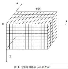
Use a matrix grid to represent the surface of the part blank
2.2 The structure definition of programming algorithm
The three-axis CNC milling machine moves on the X axis, Y axis, and Z axis. The processed blank is generally a cuboid. In the computer simulation process, we choose the more commonly used flat-end milling cutter. The surface of the blank is represented as an m×n matrix grid as shown in Figure 1. Each intersection is called a node. For each node, its relative upper surface point coordinates are fixed, and what changes is its depth and the method of drawing. In the simulation process, the depth of the node is constantly changed to express the actual situation of the blank being processed. Increase the density of the matrix grid by increasing m and n, thereby improving the simulation accuracy.
First use the related linked list to save the knife drop point and its related attributes. Use a two-dimensional array to record all relevant points on each surface and the linked list information corresponding to each point. This list is used to store the starting point of this blank, vertical processed all points on a straight line to the surface. The nodes in the linked list record the coordinates of the processing points.
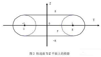
Projection on Y-Z plane of track surface
2.3 Algorithm steps:
Step1: Initialize, read in the CNC program, the attributes of the blank to be processed and the relevant information about the tool and the tool drop point, including the selection of the surface to be processed.
Step2: According to the initialization information, run the point-taking algorithm, record those points that have been processed and those points that have not been processed, to je, node selection.
In a calculation by the computer, the milling cutter traveled a straight distance. Only those nodes on the trajectory surface should consider the modification of their depth, and call these points as modified points. If the machining surface is selected as ZOY, the flat-end milling cutter walks through a straight line, and the projection of its track surface on the X-Y plane is an area composed of a rectangle and two semicircles. In order to simplify the calculation, we can move the coordinate system as shown in Figure 2:
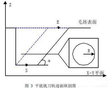
Longitudinal section of track surface of flat milling cutter
Where S is the projection of the starting point of the milling cutter on the Z-Y plane, E is the projection of the end point of the milling cutter on the Z-Y plane, the distance between S and E is 2L, and the origin is the midpoint of S and E. For any node P(y, z) který splňuje jednu z následujících podmínek, stává se modifikačním bodem:
já. -R<= z <=R a –L<= y <=L
II.-R<= z <=R a | PS|<=R
III.-R<= z <=R a | PE|<=R
Podobně, pokud se rozhodnete zpracovat jiné povrchy, metoda je podobná, kromě toho, že se změní odpovídající souřadnice.
Krok 3: Upravte výpočet hloubky bodu
Dráhová plocha frézy s plochým dnem má takovou vlastnost: Pokud je povrch zpracování vybrán jako XOY, rovina z=Z0 bude plocha s poloměrem R (jak je znázorněno na obrázku 3). Předpokládejme, že úhel mezi SE a rovinou X-Y je a, a bod modifikace je P(X,y,z),
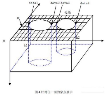
Zobrazení frézování na obou stranách součásti
Pak já. Pokud je vodorovná vzdálenost mezi P a S menší než R, hloubka P by měla být stejná jako S.
II. Pokud vodorovná vzdálenost mezi P a S není menší než R, then the depth Z of P can be obtained by the equation |(P-S)-(Z-Zs)/sinan|=R.
Podobně, pokud se rozhodnete zpracovat jiné povrchy, metoda je podobná, kromě toho, že se změní odpovídající souřadnice.
Step4: Connect the processed interval on each row and column on the surface of the part, and the corresponding maximum processing depth in the interval, respectively in the form of a linked list by row and a linked list by column. And record the maximum depth corresponding to the interval in the row (or column) in the head node of the corresponding linked list.

Linked list of CNC machining coordinate design
Jak je znázorněno na obrázku 4, for any face, the mth row: Assuming that in this row, the maximum depth between datal and data2 is h1, the maximum depth between data3 and data4 is h2, and h1>h2, the following linked list will be generated:
The generation of the linked list is dynamic, and it will be continuously modified as the processing progresses. Poté vytvořte hashovací tabulku pro každý povrch, abyste zaznamenali všechny relevantní body na každém povrchu a propojený seznam informací o hloubkových bodech odpovídajících každému bodu..
Krok 5: Je realizováno kreslení dílů.
Proces je rozdělen do dvou částí: neopracovaný vnější povrch lakované části a obalový povrch vzniklý po zpracování malby. Když se zpracovávají díly, boční hraniční body povrchu obálky musí být shromažďovány nepřetržitě. V tuto chvíli, jsou použity informace hash tabulky odpovídající každé ploše. Při kreslení, podle zpracování různých povrchů, souřadnice by měly být převedeny, aby se objevily ve stejném prostoru.
2.4 Realistické zpracování:
Implementačními nástroji tohoto algoritmu jsou VC++6.0 a OpenGL. Maticová mřížka jen vytváří “struktura” objektu. Pokud chcete, aby byly objekty realistické na počítači, musíte zvážit zpracování světla. For each node, definujte pro něj normální vektor. Úpravou hodnoty normálového vektoru při úpravě hloubky uzlu, do simulace lze přidat zpracování světla.
V příkladu popsaném na obr 5, rozměr přířezu je 300mm×300mm×200mm, a maticová mřížka je 256×256. Dvě ploché frézy s různými průměry (průměry: 14mm a 6 mm) Jsou používány. Výsledek po zpracování přířezů z různých povrchů.
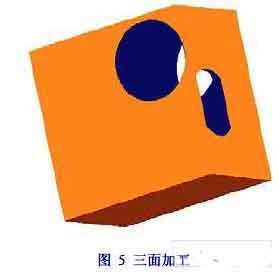
Třístranné CNC obrábění dílů
3 Závěr
V simulaci NC obrábění, kromě požadavků na přesnost simulace, proces obrábění musí být kdykoli kontrolován. V metodě tohoto článku, změna hustoty maticové mřížky může zlepšit přesnost simulace. Pro obecné potřeby, stačí mřížka hustoty 512╳512. Protože maticová mřížka se používá k zobrazení zpracovávaného obrobku, operace zoomování a otáčení obrobku jsou velmi jednoduché, které je pro uživatele výhodné pečlivě sledovat. Tento algoritmus byl aplikován v praxi a dosáhl dobrých výsledků.
 English
 العربية
 中文(漢字)
 Čeština
 Dansk
Dansk Nederlands
 Suomi
Suomi Français
 Deutsch
 Italiano
 日本語
日本語 ಕನ್ನಡ
ಕನ್ನಡ 한국어
한국어 Português
 Русский
 Slovenčina
 Español
 Svenska
 Türkçe

