Podle materiálu, konstrukční vlastnosti a technické požadavky oběžného kola, je analyzován a studován plán CNC obrábění, včetně procesu obrábění, technické potíže a přijatá technická opatření. Doporučuje se přidat požadované nálitky procesního přípravku na jeden konec oběžného kola, a navrhnout a vyvinout speciální formu přípravku, která splňuje požadavky na zpracování oběžného kola. Not only meets the CNC machining accuracy and shape tolerance requirements of the patterned parts, but also the machining efficiency is greatly improved.

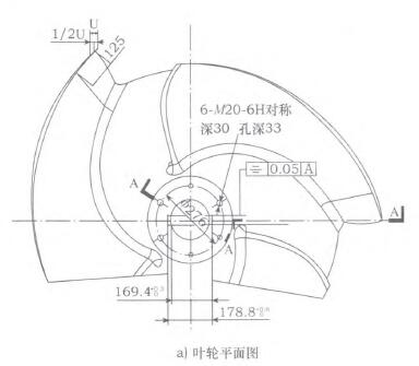
Plan view of mixed flow pump impeller

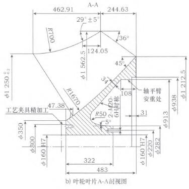
Řez A-A lopatky oběžného kola
Klíčová slova: impeller; CNC machining process; special tooling; process improvement
introduction
Vertical mixed flow pumps are widely used in power stations, power plants to transport circulating cooling water, seawater desalination, urban water supply and drainage and pumping stations, and agricultural irrigation. It has played a great role in the greening and environmental protection of the city. Because the impeller is the key part of the water pump rotation, the technical requirements are relatively high, so its precise processing is a big problem. Accurate processing can reduce the vibration caused by water flow and increase the service life of the impeller. The outlet diameter of the vertical mixed flow pump is relatively large (jako 4,1 800mm), and the coaxiality between the impeller and the center line of the corresponding hole of the pump is very important. If the coaxiality does not meet the requirements, the impeller chamber will be rubbed, and the impeller will be damaged. Proto, the machining accuracy and coaxiality of the impeller are particularly important.
1. Analysis of impeller parts materials and processing technology
1.1 Characteristics of impeller material and blank
The processing object is the impeller shown in Figure 1. Due to its complex structure, steel castings are generally used. The casting blank cutting allowance is relatively large, if the blank size is 4,1 250~4,2 000mm, the allowance (one side) is 23mm; If the blank size is 4,800-4,1 250mm, the margin (one side) is 21mm. The material of the impeller is ZGOFCRl9N19, which is austenitic stainless steel and contains Ni element. The toughness of Ni is great, which affects the cutting performance, and the tool is easily damaged by sticking. Austenitic stainless steel is also subjected to solution treatment at 1010~1150℃, and its hardness is generally between 360~400HB. Coupled with the black skin produced during casting of austenitic stainless steel, its hardness is higher. navíc, since the blade cutting is discontinuous, it is easy to cause tool collapse during cutting, so the impeller machining requires relatively high tools.

Design the process of NC machining impeller blades
1.2 Process analysis of CNC machining impeller
Due to the complex shape of the impeller, high hardness, and easy sticking to the knife during milling, its processing is difficult. The processing methods are also diverse. Mezi nimi, DVT400: 31/32 type vertical machine tool is the most widely used in processing, but it requires a high level of workers, and special tooling is required to ensure the reliability of clamping and the stability of cutting. Obecně řečeno, impeller processing has the following problems.

General impeller processing and clamping plan
Postava 1 Parts diagram of impeller
1) The alignment time is too long. The force acting on the workpiece in the radial direction (pointing to the direction of the workpiece rotation axis) during cutting is extremely easy to cause the workpiece to vibrate and cause displacement. V tuto chvíli, a second alignment is required.
2) The accuracy and process size are difficult to guarantee. The impeller blades are outer spherical and require relatively high precision. Coupled with the influence of the error of the machine tool itself, it is difficult to guarantee the accuracy of impeller machining.
3) Low production efficiency. When CNC machining impeller blades, the auxiliary time and maneuvering time are too long, especially for single-piece production.
4) It is easy to produce waste products. It is difficult to guarantee the processing accuracy and process size, which increases the scrap rate and the production cost.
2. CNC machining process for impeller blades
2.1 Determination of datum plane
According to the process requirements, select the non-machined surface as the rough reference surface. It can be seen from the impeller parts drawing shown in Figure 1 that the forming surface composed of size 13mm and R50 is 45C on the upper left side of the blade root. The inclined surface is a non-machined surface and can be used as a rough reference surface. But because it is a non-machined surface, as a reference surface, calibration is very important, and the two surfaces must be coaxial. If the reference plane is not correctly calibrated, it will affect the weightlessness of the dynamic balance. If the reference level correction deviation is too large, the dynamic balance will lose too much weight, it will definitely affect the strength of the impeller, and even cause scrap. Proto, in order to avoid adverse effects due to de-duplication, it is particularly important to calibrate the reference plane and ensure the wall thickness.
2.2 CNC machining process of impeller blades
According to the above discussion, it is necessary to clamp the upper left side 45 of the blade root. The inclined plane is calibrated, but because the impeller blade structure is three-piece, and it is a circular arc surface. If the six M20 holes on the left side of Figure 1a cannot be clamped firmly, these six holes can only be used for rough machining and clamping, so the left craft boss is thickened and six M24 screw holes are machined on it. Used for clamping. When clamping with the boss of the craft fixture on the left, first correct the forming surface composed of size 13mm and R50mm and use it as a reference, and then rough-cut 61 212.5mm outer circle and 4,1122.5mm large plane at the right end. Then use the molding surface composed of size 13mm and R50mm as the reverse reference to correct the upper, middle and lower three points of the 450 slope on the upper left side (Upper and lower points can be selected at 30mm from the outer end, and the midpoint can be selected as the midpoint of the inclined plane); Finally, rough turning and flattening the process boss plane at the left end.
If the planes at the left and right ends are deviated due to casting, a certain amount of cutting allowance can be left on both sides, which can reduce parts scrap due to excessive imbalance caused by casting deviation. With the benchmarks at both ends of the impeller, the subsequent milling process can be carried out according to the machining process of the impeller blade shown in (Table 1).
Table 1, Machining technology of impeller blade
According to the above analysis, the method of processing impellers by vertical turning must be improved to meet the needs of processing accuracy and mass production. Například, by improving the mold, high processing accuracy can be achieved, and the processing equipment is simple, and the operation and adjustment are also convenient.
3. Impeller processing tooling and its solutions
3.1 General impeller processing and clamping method
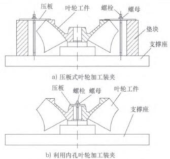
According to the general vertical lathe processing technology, when from rough machining to final finishing, the west 122.5mm outer circle, the right end face and the right end at qb282mm, turning 938mm stop, need to change the pressure plate. The pressing plate type impeller machining clamping method shown in Fig. 2a and the inner hole impeller machining clamping method shown in Fig. 2b are respectively adopted. In the process of exchanging the pressure plate, due to the long time and instability, the accuracy of the parts decreased and the drawing requirements could not be met. Also, when using the inner hole for clamping, since the +160H7 inner hole L surface is too small, the contact surface is small, and the stability during compression is relatively poor. The cutting force when processing the west 1212.5mm outer circle and its right end face is relatively large, and the material is austenitic stainless steel, which also increases the cutting difficulty. Careless cutting will cause the knife to turn over. The lighter part will be scrapped, and the severer will cause casualties. In order to improve labor productivity, ensure processing quality, and reduce labor intensity, it is necessary to improve the impeller processing and clamping method.
3.2 Improved plan for impeller processing and clamping
The impeller processing technology and its wood mold tooling improvement must start from the rough benchmark quality assurance. As described in Chapter 2 of this article, start with the non-machined surface of the outer wall of the impeller and correct the upper left side 45. The upper, middle and lower three points of the inclined plane (upper and lower two points can be selected at 30mm from the outer end, and the midpoint can be selected as the midpoint of the inclined plane). The outer ring and plane cast on the left end surface and both ends of the rough turning, reverse correction jealousy 13mm and R50mm forming surface as the reference surface. If there is a deviation between the inner wall and the outer wall of the impeller, a certain cutting allowance can be left on both walls, so that the wall thickness error caused by casting can be reduced.

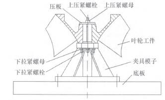
Fixture positioning and clamping impeller state
Postava 2. General clamping plan for pressing plate impeller processing
Například, when turning the right end face of qb282mm, the right end face of 122.5mm and the outer circle, you can first draw the 6-M20-6H hole line in the part shown in Figure 1a, and then drill the 6-M20-6H hole. Then during vertical turning, use the 6-M20 threaded hole L to press it on the impeller turning jig mold shown in Figure 3, turning qb282mm outer round surface. Turning l 212.5ram right end surface and its outer circle surface. Postava 4 shows the positioning of the clamp mold and the clamping state of the impeller. The wood mold tooling is suitable for batch processing of the impeller body, which makes the clamping of the impeller body reliable, convenient and fast. Such impeller body processing technology and method can easily make the processing accuracy and form and position tolerance meet the pattern requirements, and make the impeller body processing more reasonable Hd 0|.
3.3 The impeller machining fixture mold and its positioning instructions
The mold structure of the impeller turning fixture is shown in Figure 3. Position the part with tkl60 L, place the part on the mold, tighten the lower end with a nut, to je, use the fixture mold shown in Figure 4 to fit the 6 threaded holes on the left end of the part. První, tighten six M20 double-ended studs with a length of about 120mm on the part, and then clamp the pressure plate with M30 studs at the center of the mold and the center of the part. The reference positioning adopts the contact part between the left end face of the impeller body shown in Figure 1a and the plane of the clamp, which is equivalent to 3 supporting points restricting 3 degrees of freedom;
The contact between the 6160 inner hole surface of the left end of the impeller body and the side surface of the boss of the fixture is equivalent to two supporting points restricting two degrees of freedom, and the last degree of freedom is guaranteed by the pressure plate.
Postava 3, the structure of the impeller turning fixture mold
4. Závěr
The impeller is processed under the condition of incorrect reference plane, which seriously affects the balance of the impeller, causes the impeller and the bearing to vibrate, and damages the impeller chamber and other parts. If the water pump fails, it will seriously endanger the operation safety of the power plant, and even cause major accidents. Through the use of improved fixture molds and other operations, the machining accuracy and shape tolerances fully meet the design requirements of the pattern, and the machining efficiency is increased by about 40%. The fixture mold positioning method is reasonable, the clamping is reliable, convenient and fast, and the processing quality of the impeller remains stable. It satisfies batch manufacturing, improves labor productivity, reduces production costs, improves economic efficiency, and increases the competitiveness of products in the market.
 English
 العربية
 中文(漢字)
 Čeština
 Dansk
Dansk Nederlands
 Suomi
Suomi Français
 Deutsch
 Italiano
 日本語
日本語 ಕನ್ನಡ
ಕನ್ನಡ 한국어
한국어 Português
 Русский
 Slovenčina
 Español
 Svenska
 Türkçe

