 English
 العربية
 中文(漢字)
 Čeština
 Dansk
Dansk Nederlands
 Suomi
Suomi Français
 Deutsch
 Italiano
 日本語
日本語 ಕನ್ನಡ
ಕನ್ನಡ 한국어
한국어 Português
 Русский
 Slovenčina
 Español
 Svenska
 Türkçe
Při výrobě nástrojů a forem se objevují složité obrysy, a jsou sériově vyráběnými produkty. Před vznikem CNC obráběcích strojů, kovací zápustky a zápustky používané v automobilovém průmyslu byly vyráběny převážně ručně. Po 70. letech 20. století, CNC obráběcí stroje jsou široce používány při výrobě nástrojů a forem. Základní obrysy složitých profilů se obvykle zpracovávají frézováním, a okolní CNC obráběcí stroje jsou zpočátku nastaveny na tříosé propojení.
Po vstupu do 80. let, pětiosé frézky byly široce používány při komplexním zpracování povrchů. Obrys obrobku po frézování je velmi blízký konečnému tvaru obrobku, ale poslední dokončovací proces je stále ruční. Koncem 80. let 20. století, technologie vysokorychlostního řezání se postupně vyvíjela a dozrávala, a jeho aplikace v průmyslové výrobě se neustále zdokonalovala v oblasti obráběcích strojů, řezné nástroje a další související technologie. Protože vysokorychlostní řezání může zdvojnásobit rychlost posuvu, rozteč posuvu lze snížit bez snížení efektivity výroby. To poskytuje předpoklad pro zlepšení tvarové přesnosti obrobku a snížení drsnosti povrchu. V současnosti, většina obrobků zpracovávaných vysokorychlostním frézováním již nepotřebuje poslední ruční opracování, but can be directly put into use.
5-osové obrábění složitých profilů
New tool materials: such as alumina-based ceramics, silicon nitride-based ceramics, cermets, slinutý karbid, especially the continuous development of superhard coatings, making hard face milling possible. The mold surface can be milled to shape after quenching, thereby avoiding deformation caused by quenching after milling. This not only simplifies the machining process, but also improves the accuracy of the workpiece.
Navíc, with the application of precision forging in die manufacturing, the die blank after forging already has its designed basic shape, and the remaining machining allowance is insignificant compared with the milling of the entire blank. V tomto případě, in addition to milling, it can also be processed by high-efficiency grinding. Compared with hard face milling, high-efficiency grinding can not only improve the shape accuracy of the workpiece, but also improve the surface roughness of the workpiece. There are many high-efficiency grinding methods, usually high-speed grinding with spherical grinding wheels and belt grinding with small-diameter belt wheels.
Type of milling cutter
Three-dimensional free-form surfaces in tools and molds are usually processed on a 5-axis machining center. Since the material of the workpiece is mostly alloy steel or tool steel, the structure of the machine tool and the numerical control system must consider the requirements of productivity and workpiece accuracy in the processing process, and make appropriate layout and optimization based on this. In order to ensure that the machine tool does not undergo too much deformation when cutting various mold materials, the machine tool stiffness should be the first priority when determining the machine layout. Larger axis machining center, most of a gantry structure, some small-sized five-axis machining center is also sometimes used high column structure.
Since the beginning of the 1990s, almost all complex shapes have been processed by high-speed cutting in production. The purpose is to improve production efficiency, reduce product cost, and at the same time improve the shape accuracy of the workpiece and reduce the surface roughness. In order to meet the needs of high-speed cutting, the spindle of the machine tool almost without exception uses an electric spindle. The spindle speed is continuously variable according to the diameter of the tool used, and the speed ranges from several thousand revolutions per minute to tens of thousands of revolutions per minute. The drive system of the sliding table is also different from conventional machining centers in high-speed cutting. Commonly used system with high-speed drive nut screw assembly and linear motor drive, a maximum feed speed can reach 100m / min or more.
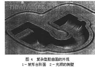
The appearance drawing of CNC machining complex cavity surface
When processing complex surfaces, the CNC system of the machine tool must also meet some special requirements. Například, CNC machining programs for complex surfaces are generally generated on CAD/CAM software. A profiled program often requires several megabytes (Byte) of storage space, a již není možné přenášet NC programy pomocí diskety. Proto, CNC systém musí mít funkci síťového propojení s jinými počítačovými systémy, aby mohl přijímat CNC program přímo z CAD/CAM. Navíc, numerický řídicí systém musí také přijmout pokročilou řídicí technologii, Předně, vyžaduje funkci LookAhead. Jinými slovy, než obráběcí stroj zpracuje určitou stopu, datový systém předem analyzuje povrch, který má být zpracován. Podle zakřivení každého bodu zakřivené plochy a vazebního vztahu každého sousedního bodu, rychlost posuvu obráběcího stroje je vhodně nastavena pro dosažení nejvyšší produktivity za předpokladu zajištění přesnosti obrobku. Aby se omezily dynamické chyby při zpracování, nová data pro opravu chyb serva pomocí konvenčního tandemového systému již nejsou proporcionální integrální derivací (PID) ovladač, místo použití stavového regulátoru kompenzací parametrů stavu polohy a rychlosti. Použití tohoto typu regulátoru může zcela eliminovat chybu hystereze měniče, kompenzovat nelineární chybu způsobenou mezerou nebo třením, a dokonce kompenzovat určité vibrace obráběcího stroje. Tak, aby byly splněny požadavky na zlepšení tvarové přesnosti obrobku a snížení drsnosti povrchu.
Nastavení řezné dráhy povrchu dutiny
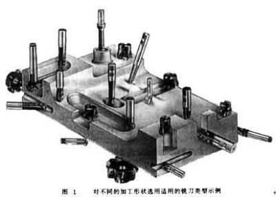
Nástrojový systém hraje rozhodující roli v efektivitě výroby a kvalitě zpracování při zpracování složitých profilů. Při výběru systému řezných nástrojů, we must first start from the geometry of the parts to be processed, and reasonably use the types of cutting tools. Jak je znázorněno na obrázku 1, the geometry of each part is very different. If only a ball-end milling cutter is used for processing, a ball-end milling cutter with a small diameter must be selected, which makes it difficult to improve processing efficiency. Navíc, the arc radius of some parts is so small that it cannot be processed even with a small ball end mill. Proto, taking into account the requirements of both production efficiency and workpiece shape, other types of milling cutters must be equipped on the five-axis machining center for processing complex profiles, such as end mills and three-face milling cutters.
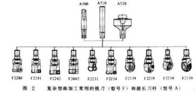
Postava 2 shows some types of milling cutters. As long as the size permits, regardless of the shape of the tool, the cutting edge should be a milling insert with a convertible clamp. Such knives can be combined in a variety of ways because of the blade and the body, and the blade and the body can be produced by different companies. Proto, large-scale specialized production can be formed, which not only helps to improve the quality of the tool, but also helps to reduce the production cost of the tool.
V současné době, most of the indexable blades on the market use CVD coated carbide blades. In order to achieve higher pseudo-abrasion resistance, the indexable inserts are all multi-layered coatings. Bizhi Al2O3 can improve the chemical stability of the blade. TiN and TiCN can enhance the wear resistance of the blade. In order to enhance the sharpness of the blade, in addition to the low-temperature CVD method, the coating can also be produced by the PVD method. Some processing has very strict requirements on the blade. The blade must have a sharp cutting edge to reduce the roughness of the finished surface, but also have a high wear resistance to ensure the shape accuracy of the workpiece. V tomto případě, a combination of multiple coatings must be used. In order to ensure that the use of some blades is foolproof, the number of coating layers can be as high as 100.
The life of the tool is closely related to the feed rate, cutting speed and depth of cut. The optimal cutting amount is often a small range, which should be determined according to the specific tool and workpiece material.
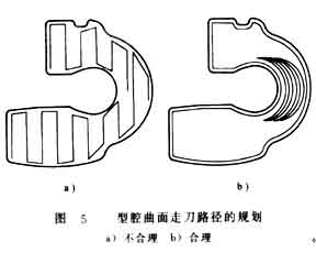
Navíc, cutting strategies such as: The planning of the tool path, the normal vector of the tool axis surface (the normal direction of the surface at this point) or the different methods along the surface tangent vector (the tangent direction of the surface at this point), atd., are also a key factor for processing complex surfaces . It not only affects the surface roughness of the processed workpiece, but also affects the shape and dimensional accuracy of the workpiece. Postava 3 shows the different cutting strategies used when machining a cylindrical surface. For cutting in the circumferential direction, the tool path needs to be interpolated in two-axis linkage. When cutting along the generatrix direction, the tool only needs to perform single-axis interpolation. Navíc, different cutting methods have great differences in tool wear. The tool wear during down milling is significantly lower than that of up milling, a opotřebení při vratném frézování je mnohem větší než u jednosměrného frézování.
Aby se zlepšila stabilita procesu obrábění, při optimalizaci strategie řezání, musí být zajištěna kontinuita řezání, a řezný pohyb a zdvih naprázdno musí být co nejvíce omezeny, aby se zkrátila doba řezání. Při hrubém frézování oceli, musí zajistit plynulé sousledné frézování, aby se minimalizovala špička řezného kotouče během řezání množství kolísání.
Při zpracování obrobku znázorněného na obr 4, pokud je použito zpracování úseku trajektorie řezu znázorněné na obrázku 5a; Pohyb nástroje je velmi nerozumný, řezné podmínky jsou velmi nevyhovující, doba zpracování je 33 minut, a drsnost povrchu obrobku je 6-9μm. If you switch to the circle-cutting path shown in Figure 5b for processing, the processing time is about 27 minut. Ve stejnou dobu, the roughness of the workpiece can also be reduced to 2 ~ 4μm.