 English
 العربية
 中文(漢字)
 Čeština
 Dansk
Dansk Nederlands
 Suomi
Suomi Français
 Deutsch
 Italiano
 日本語
日本語 ಕನ್ನಡ
ಕನ್ನಡ 한국어
한국어 Português
 Русский
 Slovenčina
 Español
 Svenska
 Türkçe
5-axis machining of base parts
The high-performance 5-axis CNC milling machining center, the CNC system has the space coordinate system rotation and the inclined tool compensation function, which provides the possibility for the machining of some parts that require inclined surface machining and high machining accuracy. Při obrábění na nakloněné rovině, je obtížné sestavit obráběcí program, protože souřadnicový systém se v prostoru mění. Potřeba prolomit konvenční režim programovacího myšlení pro programování, a speciální zpracování programu. This article discusses this issue in conjunction with the actual processing of model products.
Such parts are often encountered in the production process of products, and they need to be punched, bored, and milled on the inclined surface. Or it needs to be processed on several inclined surfaces with different directions and different slopes in the same clamping, a každý nakloněný povrch má vyšší požadavek na geometrickou toleranci. The conventional method of processing such parts is to pull the head of the bed, otočte pracovní plochu nebo použijte modulární přípravek. Pokud se směr zpracování nebo poloha zpracování liší, je nutné druhé upnutí a opětovné vyrovnání, a proces zpracování je extrémně těžkopádný. Z důvodu omezení polohování upínání a samotného obráběcího stroje, nelze zaručit přesnost obrábění dílů. Například, in the T×× table body processing, there are many holes on the inclined surface, a speciálně tvarovaný povrch není snadné upnout, the positioning reference is not good, and the error accumulation caused by multiple clamping, sometimes the hole margin error exceeds 1mm.
In order to solve the processing problem of this kind of parts, prostřednictvím neustálého zkoumání a neustálého zlepšování procesních metod, combined with the factory’s existing machine tools, a five-axis CNC milling machining center was selected to solve this problem. Vybraný obráběcí stroj je 5osý spoj. In addition to 3 lineární osy, má také dvě rotační osy (C osa: -360°~360°) a kyvnou hlavou (osa B: 0°~110°). The control system used is FANUC160i, which has the functions of space coordinate system rotation and inclined tool compensation.
From the perspective of realizing bevel processing, multiple bevels in different directions and different angles can be punched, nudný, tapped, milled and other processes can be completed after one clamping. Reduce the number of clamping times, reduce labor intensity, shorten the production cycle of the product, A více důležitě, improve the processing accuracy of the parts and ensure the consistency of product quality.
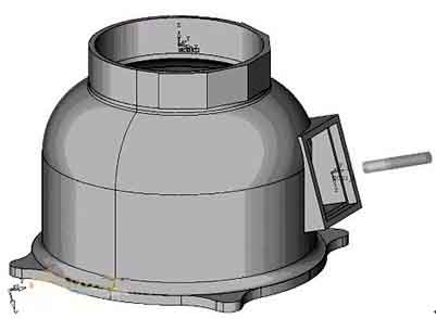
Take the processing of a certain base part as an example. The parts are shown below: To process this base, je vidět, že obráběcí stroj by měl dokončit interpolaci 2osého propojení v rovinách XZ a YZ a výkyvný pohyb hlavy vřetena. Protože aby byl nástroj kolmý k obrobené ploše, vřeteno musí dokončit kývavý pohyb hlavy. Having a rotating head involves a series of multi-axis machining issues such as pendulum length. Proto, it is necessary to use multi-axis programming means to complete. Programming and machine tool debugging are difficult, which puts higher demands on programmers and machine operators. V praktických aplikacích, zohlednění faktorů, jako je zajištění bezpečnosti obráběcího stroje, it is necessary to simulate the processing process and perform multiple air cuts to ensure that the program is correct before formal processing can be performed. Navíc, algoritmus víceosého programu je poměrně komplikovaný, a je třeba vzít v úvahu vliv faktorů, jako je délka kyvadla. Pro určitý obráběcí stroj musí existovat specifické následné zpracování, but the post-processing is often due to the difference in algorithms and control positions, as well as the influence of calculation stability. Program získaný prostřednictvím softwarového následného zpracování je často obtížné splnit požadavky na přesnost výkresů součástí z hlediska přesnosti řízení..
The analysis shows that the direct cause of the increase in programming difficulty is the appearance of the inclined plane. Proto, pokud lze dosáhnout toho, aby se rovina obrábění shodovala s nakloněnou rovinou, pak bude tento druh problému transformován do dvouosého semi-processingového programovacího problému, a značně se sníží obtížnost programování. Proto, it is conceivable to use the coordinate system conversion function of the machine tool (Příkaz G68) aby se rovina obrábění shodovala s nakloněnou rovinou. The second tool length compensation command (G432) is used to add the tool length in the vertical direction of the inclined plane. Po výše uvedeném zpracování, problém zpracování úkosu je transformován do rovinného zpracování, thus the programming difficulty is greatly reduced. Pokud potřebujete zpracovat více nakloněných rovin současně, stačí otočit osu C na C0 (nulovou polohu pracovního stolu, směr nulové polohy je stejný jako směr otáčení vřetena), a poté realizovat zpracování otočením souřadnicového systému a zvětšením délky nástroje. Pokud je tvar zpracování poměrně jednoduchý, programming can be done manually. This makes it possible to realize the machining of multiple inclined surfaces, multiple positions, a vícenásobné výměny nástrojů při jediném upnutí CNC obráběcího stroje.
The program structure is as follows:
%
N0100O0008 (program name)
N0102M6T1; (tool change)
N0104G0G90G56X400Y200Z260B0C0; (Move to the reference point)
N0106G432X200Z150H1Bω; (add the knife length in the direction perpendicular to the inclined plane)
N0108M3S3000; (Spindle forward rotation)
N0110M8; (open cutting fluid)
N0112G68X188Y0Z60I0J1K0Rω; (Coordinate system conversion, ω is the angle of rotation of the main shaft from zero to perpendicular to the inclined plane)
……
N0200G69; (cancel coordinate system rotation)
N0202G492X200Z300; (Slope tool compensation canceled, move to a safe position)
N0204M9; (cutting fluid off)
N0206Cα; (C axis rotation, α is the minimum angle between the vertical line of the nth inclined plane to be processed and the C0 position)
N0208G0G90G56X400Y200Z260B0C0; (Move to the reference point)
N0210G432X200Z150H1Bωn; (add the knife length in the direction perpendicular to the inclined plane)
N0212G68X188Y0Z60I0J1K0Rωn; (Coordinate system conversion, ωn is the angle of rotation when the main shaft turns from zero to perpendicular to the slope)
…
N0200G69; (cancel coordinate system rotation)
N0202G492X200Z300; (Slope tool compensation canceled, move to a safe position)
N0204M9; (cutting fluid off)
N0204M30; (program ends, return to program head)
Although the bevel machining has been achieved in the above discussion, it is limited to drilling, nudný, klepnutím, and milling on the bevel. The simple shapes composed of straight lines and arcs are limited to manual programming. If the milling shape is more complicated. Such as milling equation curves, three-dimensional curved surfaces, and lettering on an inclined plane, how to program it?
Even when these similar shapes are processed on a flat surface, manual programming is not possible, and it can only be completed by CAM software. Through careful study of machine tools and CAM software, a set of software programming combined with manual programming was found to be an effective way to complete the processing and programming of such parts.
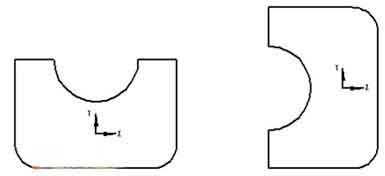
The analysis shows that in ordinary three-axis milling programming, the direction of the tool axis is always perpendicular to the XOY plane. But when the spindle deviates from the original vertical direction and the tool plane is inclined, how can the program generated on the XOY plane run correctly on the inclined plane? The analysis shows that although the coordinate system has been rotated, if the relative position of the figure (A) in the original coordinate system and the shape to be processed on the inclined plane (b) and the relative position in the new coordinate system are kept consistent on the XOY plane . Then the program generated on the XOY plane can be directly applied to bevel machining.
According to the influence of the swing head movement of the machine tool on the graphics position, the analysis shows that when drawing on the XOY plane, the graphics should be rotated 90° counterclockwise with the programming origin as the rotation center (the rotation angle should be determined according to the specific conditions of the machine tool). Takto, the graphic position in the CAM software is kept consistent with the actual machining position. By adding and modifying the program head and program end, to je, adding coordinate system conversion and inclined tool compensation, software programming and manual programming are combined. This realizes the machining of arbitrary complex shapes such as milling equation curves, three-dimensional curved surfaces, and lettering on the inclined surface.
5-axis milling equation curve on inclined plane, three-dimensional surface
Through the actual machining verification, it is confirmed that the method is within the allowable range of the machine function and stroke, and the programming of this method can realize the machining programming of any complicated shape on any inclined plane.
The following figure shows an example of processing a three-dimensional curved surface on a 52° inclined plane:
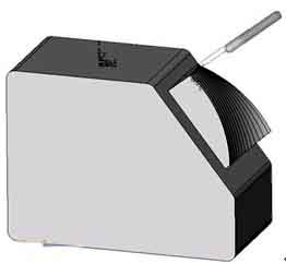
Machining three-dimensional curved surface