 English
 العربية
 中文(漢字)
 Čeština
 Dansk
Dansk Nederlands
 Suomi
Suomi Français
 Deutsch
 Italiano
 日本語
日本語 ಕನ್ನಡ
ಕನ್ನಡ 한국어
한국어 Português
 Русский
 Slovenčina
 Español
 Svenska
 Türkçe
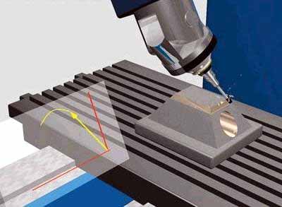
مع الزيادة في تصميم الأجزاء المنحنية المتعددة الأوجه والمعقدة, 5-سوف تمثل المعالجة المحورية نسبة متزايدة من المعالجة باستخدام الحاسب الآلي. لأن التصنيع باستخدام الحاسب الآلي ذو 5 محاور يضيف درجتين من حرية الدوران, فهو يزيد من صعوبة حساب محاكاة حركة التصنيع باستخدام الحاسب الآلي والتحقق من تداخل الأداة, خاصة عند تصنيع الأجزاء ذات الأشكال المعقدة للغاية. لذلك, in order to ensure that 5-axis CNC machine tools perform high-efficiency and high-quality milling processing, the design of 5-axis machining tool path generation and interference checking software will become a major issue.
The feature projection method is suitable for 5-axis CNC machining tool interference processing, إنه, the machining surface is discretized into a series of surface feature points. Whether the tool interference occurs can be judged by whether the feature point enters the inside of the tool surface. في نفس الوقت, the machining surface and the tool surface are projected onto a specific plane, and only the feature detection points in the curved surface area of the enveloping tool projection graph are checked for interference, which improves the efficiency of interference detection.
منع تداخل الأداة في الطحن ذو 5 محاور
1. Inspection method for tool interference
Coordinate system and coordinate transformation
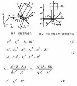
كما هو مبين في الشكل 1, the local coordinate system L of 5-axis circular cutter milling is represented as XL axis, YL axis and ZL axis. The YL axis always points to the cutting direction f of the tool contact (referred to as CC point) OL. The ZL axis points to the normal direction n of the surface, and the XL axis is determined by the right-hand rule of the YL axis and the ZL axis. The tool generally rotates around the XL axis from the ZL axis to the YL axis by a lead angle (heel angle) أ, and rotates around the ZL axis one by one side slip angle b. فضلاً عن ذلك, the tool coordinate system T (XT, YT, ZT) can also be defined at the tool location point (CL point for short) OT. The YT axis points to the direction of the line connecting the CL point and the CC point. The ZT axis is the tool axis vector direction, and the XT axis is the direction determined by the right-hand rule of the YT axis and the ZT axis. The coordinate origin is located at the tool center point (ie CL point) OT. In order to simplify the interference check, the tool surface with a relatively regular shape is used as the reference for interference check. The machined surface is discretized to express the shape of the surface in the form of a set of characteristic points. The original data of these feature points are expressed in the world coordinate system W, so the feature point data must first be transformed from the world coordinate system W (OW-XW, YW, ZW) to the local coordinate system L (OL-XL, YL, ZL) ). ثم يتم تحويله من نظام الإحداثيات المحلي L إلى نظام الإحداثيات الأداة T (أو تي-XT, YT, ZT).
Interference check method
إذا تم تحديد الأداة ورأس الطاقة, حجم نظام الأداة (أداة ورأس السلطة) معروف. Whether the tool system interferes with the machined surface can be determined by judging whether the characteristic point P enters the inside of the tool surface. كما هو مبين في الشكل 2, إنها العلاقة الموضعية بين نظام الأداة والسطح المُشكل عند معالجة السكين الحلقي. في نظام إحداثيات الأداة, دع إحداثيات النقطة المميزة P تكون PI (اكس بي تي, Ypt, زبت). وفقًا للأجزاء المركبة المختلفة لنظام الأداة, تنقسم القيمة الإحداثية Zpt للنقطة المميزة P إلى 4 أقسام للحكم. وفيما يلي التفاصيل:
5-axis milling stroke setting formula
When the feature point P is within the range of u1, no interference will occur.
When the characteristic point P is in the range of u2, there are two situations, and the torus is divided into two parts:
The small cylindrical part P1 and the circular ring part P2. When the feature point is involved in the cylindrical part P1, tool interference occurs, إنه, it is satisfied
where R represents the radius of the tool, and R1 represents the radius of the ring of the circular tool.
When the feature point is involved in the ring part P2, tool interference also occurs, إنه, it is satisfied
in the style
If the feature point P does not enter the parts P1 and P2, no tool interference will occur.
عندما تكون النقطة المميزة P ضمن نطاق u3, عندما تكون المسافة بين النقطة المميزة P ومحور ZT أقل من نصف قطر الأداة, tool interference occurs, which is satisfied
خلاف ذلك, no tool interference will occur.
When the characteristic point P is in the range of u4, الوضع هو نفس الوضع 3, as long as the tool radius R in the formula (3) is replaced with the power head radius d/2 for judgment.