 English
 العربية
 中文(漢字)
 Čeština
 Dansk
Dansk Nederlands
 Suomi
Suomi Français
 Deutsch
 Italiano
 日本語
日本語 ಕನ್ನಡ
ಕನ್ನಡ 한국어
한국어 Português
 Русский
 Slovenčina
 Español
 Svenska
 Türkçe
مع زيادة التصميم السطحي المعقد للأجزاء في الصناعة الحديثة, 5-سوف تمثل المعالجة المحورية نسبة متزايدة من المعالجة باستخدام الحاسب الآلي. نظرًا لأن التصنيع باستخدام الحاسب الآلي ذو 5 محاور يضيف درجتين من حرية الدوران, فهو يزيد من صعوبة حساب محاكاة حركة التصنيع باستخدام الحاسب الآلي وفحص تداخل الأداة, خاصة عند تصنيع الأجزاء ذات الأشكال المعقدة للغاية. لذلك, in order to ensure that the five-axis CNC machine tool performs high-efficiency and high-quality milling processing, the development of five-axis machining tool path generation and interference checking software will become a major issue for researchers.
proposed a feature projection method suitable for five-axis CNC machining tool interference processing, which is to discretize the machined surface into a series of surface feature points. Whether the tool interference occurs can be judged by whether the feature point enters the inside of the tool surface. في نفس الوقت, the machined curved surface and the tool surface are projected onto a specific plane, and only the feature detection points in the curved surface area including the tool projection graphics are subjected to interference inspection, which improves the efficiency of interference detection.
1. Interference check method
Coordinate system and coordinate transformation
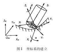
Establishment of 5-axis coordinate system
كما هو مبين في الشكل 1, the local coordinate system L for NC machining of five-axis circular cutter is represented as XL axis, YL axis and ZL axis. The YL axis always points to the cutting direction f of the tool contact (CC point for short) OL, and the ZL axis points to the normal direction outside the surface n. The XL axis is determined by the right-hand rule of the YL axis and ZL axis. The tool generally rotates around the XL axis from the ZL axis to the YL axis by a lead angle (heel angle) أ, and rotates around the ZL axis one by one slip angle b. فضلاً عن ذلك, the tool coordinate system T (XT, YT, ZT) can also be defined at the tool location point (CL point for short) OT. Wherein YT axis pointing point and CC-dot chain line CL direction, ZT axis direction of tool axis vector, XT axis direction is determined by the right hand rule and YT ZT axis of the shaft. The coordinate origin is at the tool center point (ie CL point) OT. In order to simplify the interference check, the tool surface with a relatively regular shape is used as the reference for interference check. The processed surface is discretized to express the surface shape in the form of a set of characteristic points. The original data of these feature points are expressed in the world coordinate system W, so the feature point data must first be transformed from the world coordinate system W (OW-XW, YW, ZW) to the local coordinate system L (OL-XL, YL, ZL) ). ثم يتم تحويله من نظام الإحداثيات المحلي L إلى نظام الإحداثيات الأداة T (أو تي-XT, YT, ZT).
طريقة فحص التداخل لتصنيع القطع الدائري ذو 5 محاور
Interference check method
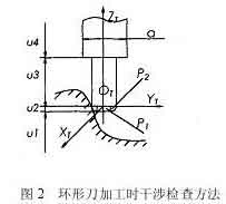
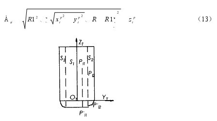
إذا تم تحديد الأداة ورأس الطاقة, حجم نظام الأداة (أداة ورأس السلطة) معروف. يمكن تحديد ما إذا كان نظام الأداة يتداخل مع السطح المُشكل آليًا من خلال الحكم على ما إذا كانت نقطة الميزة P تدخل إلى سطح الأداة. كما هو مبين في الشكل 2, إنها العلاقة الموضعية بين نظام الأداة والسطح المُشكل عند معالجة السكين الحلقي. في نظام إحداثيات الأداة, دع إحداثيات النقطة المميزة P تكون PI (اكس بي تي, Ypt, زبت). وفقًا للأجزاء المركبة المختلفة لنظام الأداة, تنقسم القيمة الإحداثية Zpt للنقطة المميزة P إلى 4 أقسام للحكم. وفيما يلي التفاصيل:
When the feature point P is within the range of u1, no interference will occur.
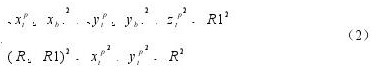
When the characteristic point P is in the range of u2, there are two situations, the torus is divided into two parts: the small cylindrical part P1 and the circular part P2. When the feature point is involved in the cylindrical part P1, tool interference occurs, إنه,
where R represents the radius of the tool, and R1 represents the radius of the ring of the circular tool.
When the feature point is involved in the ring part P2, tool interference also occurs, which is satisfied
5 axis milling tool interference calculation formula
in the style
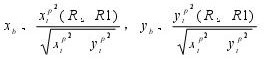
5-axis machining interference calculation formula
If the feature point P does not enter the P1 and P2 parts, no tool interference will occur.
عندما تكون النقطة المميزة P ضمن نطاق u3, عندما تكون المسافة بين النقطة المميزة P ومحور ZT أقل من نصف قطر الأداة, tool interference occurs, which is satisfied
خلاف ذلك, no tool interference will occur.
عندما تكون نقطة الميزة P في نطاق u4, الوضع هو نفس الوضع 3, طالما أن نصف قطر الأداة R في المعادلة (3) يتم استبداله بنصف قطر رأس الطاقة d/2 لإصدار الحكم.
تسمى النقاط المميزة للسطح المنحني التي تتداخل مع نظام الأداة بنقاط التداخل. اكتشف جميع نقاط التداخل وفقًا للطريقة المذكورة أعلاه, وحساب مقدار التداخل في الاتجاه الشعاعي لكل نقطة تداخل, ثم استخدم الطريقة المناسبة لإزالة التداخل.
طريقة عرض الميزة لفحص التداخل
Project the tool system and the feature points of the curved surface onto a two-dimensional plane (projection plane), and divide the machined surface into a series of squares by taking a reasonable distance on the two-dimensional projection plane. كما هو مبين في الشكل 3, when the square is completely covered by the contour of the projected tool system, it is recorded as a complete square. The surface feature points in this area may interfere with the tool system;
When the square is not intersected by the contour of the projected tool system at all, it is recorded as a non-square and it is impossible to interfere with the tool system;
When the square part is covered by the contour of the projected tool system, it is recorded as a partial square. In order to further reduce the number of feature points inspection, a quadtree segmentation process is performed on part of the squares, non-squares are deleted, and the feature points that may interfere with each other are re-edited in the order of regions, and then the coordinate transformation and interference inspection are performed.
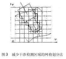
Net division method for reducing interference detection area in NC machining
2. Interference elimination method:
Rotating tool axis
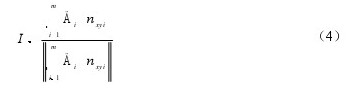
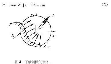
At a tool location point, there are m surface feature points that interfere with the tool system. Considering the interference situation of m interference points comprehensively, an optimal direction to eliminate interference can be found to eliminate the interference of the tool most effectively. For this reason, a new concept of “طائرة إلغاء التداخل” تم تقديمه. قم بإسقاط المتجهات العادية السطحية عند نقاط التداخل m على مستوى XTYT لنظام إحداثيات الأداة T. لنفترض أن إسقاط المتجه الطبيعي للسطح عند نقطة التداخل على المستوى XTYT هو nxyi (أنا = 1, 2, …, م), ومكون التداخل لنقطة التداخل على المستوى XTYT هو Dt (أنا = 1, 2, …, م) . كما هو مبين في الشكل 4, يمكن الحصول على متجه إلغاء التداخل من خلاله
طريقة الكشف عن التداخل لمحور الأداة الدوارة
بعد ناقل إلغاء التداخل I (سكس, سي, سز) يتم حسابه من الصيغة (4), يشكل متجه إلغاء التداخل I والمحور ZT مستوى إلغاء التداخل. دع متجه الضرب المتقاطع للمحور ZT ومتجه الإزالة I يكون K. على مستوى موازي لل “طائرة القضاء على التدخل”, the interference elimination angle d that calculates how much the tool is inclined around the K axis I can just eliminate the tool interference. كما هو مبين في الشكل 5. Assuming that the interference point Pi (أنا = 1, 2,…, م) is excluded from the surface of the tool system, the minimum angle required is di (أنا = 1, 2,…, م). Then the interference cancellation angle d is the maximum value of all angles di
Interference cancellation vector method
To exclude the interference point Pi from the tool system, the interference point Pi is fixed, and the tool system rotates around the K axis in the I direction. It is equivalent to the angle of rotation di of the interference point Pi relative to the tool system and the tool coordinate system in the plane of the parallel interference elimination plane IOTZT. Take the ring knife as an example to analyze.
كما هو مبين في الشكل 5, the rotation axis of the tool system passes through the center point O1 of the arc of intersection of the elimination plane IOTZT and the toroidal surface of the tool, and is parallel to the vector K, passes the interference point Pi, and is parallel to the elimination plane IOTZT. As a section plane, the intersection line between the section plane and the torus of the tool is a quartic curve, and the intersection line with the cylindrical surface is two straight lines. There are two situations in which the axis of the ring knife rotates. When the interference point Pi falls into the circular knife cylinder, the rotation angle di is ∠PiOPi’ (Figure 5a), and the calculation formula is
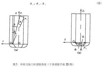
Eliminate interference angle during ring cutter processing
and the angle d1 is calculated as follows
At that time, the point Pi intersects the cylindrical surface section line during the rotation, and the calculation formula for d2 is
When the point Pi does not intersect the cylindrical section line during the rotation, the point Pi’ may intersect the quartic curve of the circular section or the section line of the bottom plane of the tool. The calculation of the angle d2 is more complicated when it intersects the quartic curve of the circular section. من أجل تبسيط الحساب, the rotation angle is treated conservatively. في هذا الوقت, the calculated angle d2 is larger than the actual angle, but it has no effect on the tool interference processing. يتم تدوير جميع نقاط المعالجة المحافظة Pi لتتقاطع مع المستوى السفلي للأداة, والزاوية d2 تساوي
كما هو مبين في الشكل 5(ب), عندما تقع نقطة التداخل Pi في حلقة السكين الدائرية, يتم أيضًا التعامل مع زاوية الدوران بشكل متحفظ. يتم تدوير جميع النقاط Pi لتتقاطع مع المستوى السفلي للأداة, the rotation angle di is ∠PiOPi’, وصيغة الحساب هي نفس المعادلة (6), حيث يتم حساب الزاويتين d1 و d2 على النحو التالي
عند رفع السكين, تتقاطع نقطة التداخل مع السطح القوسي لحافة السكين
عندما يكون القاسم في الصيغة (11) أصغر من البسط, the point Pi’ لا يمكن أن تتقاطع مع المستوى السفلي للأداة أثناء التدوير. في هذا الوقت, لا يمكن إزالة التداخل عن طريق تدوير محور الأداة, لكن احتمالية حدوث هذه الحالة ضئيلة للغاية.
يمكن لنفس المبدأ التعامل مع نقاط التداخل في أسطوانة رأس الطاقة.
على الرغم من أن نظام الأداة يمكنه إزالة نقاط التداخل عن طريق تدوير الزاوية d في الاتجاه I, قد يتداخل نظام الأداة مع نقاط ميزات السطح الأخرى أثناء التدوير. لذلك, بعد تدوير نظام الأداة, يجب حساب متجه محور الأداة الجديد ويجب إعادة إنشاء نظام إحداثي جديد للأداة. ثم تحقق من التداخل مع السطح المنحني. عندما لا يمكن القضاء على ظاهرة التداخل عن طريق تدوير محور الأداة, يتم استخدام طريقة رفع الأداة على طول محور الأداة للتخلص منها.
طريقة رفع السكين
عند استخدام طريقة رفع الأداة على طول محور الأداة للتخلص من التداخل, ينبغي حساب مقدار رفع الأداة على طول اتجاه ZT. بالنسبة لنقاط التداخل m Pi (أنا = 1, 2, …, م). احسب مقدار رفع الأداة Dzi (أنا = 1, 2,…, م) مستبعدة من كل نقطة التدخل, وأيضا خذ أكبر مبلغ كأداة رفع المبلغ Dz.
كما هو مبين في الشكل 6. عند استخدام السكين الدائري في التصنيع باستخدام الحاسب الآلي, هناك طريقتان لحساب مقدار رفع الأداة. عندما تقع نقطة التداخل Pi في أسطوانة الأداة S1 بنصف قطر (ص-ر1), الأداة ترتفع, وتتقاطع نقطة التداخل أخيرًا مع المستوى السفلي للأداة. يتم حساب مبلغ الرفع كما
عندما تقع نقطة التداخل Pi داخل جسم الحلقة S2 بفارق نصف قطر قدره R1, تتقاطع نقطة التداخل مع السطح القوسي للشفرة عند رفع الأداة, ومبلغ الرفع هو:
(1) تحديد نقطة CC من السطح المنحني, المتجه العادي n وأداة تمرير المتجه f, calculate the CL point of the tool, establish the corresponding coordinate system, and calculate the initial tool axis vector Ti (أنا = 1, 2, …, ن);
(2) For a tool location point, select a specific plane, and project the tool system and the machining surface onto the plane;
(3) The processing surface is divided into a network on the projection plane to obtain a series of square regions. Use the tag Tag to indicate the nature of the square. When Tag=1, it is a complete square and accept; When Tag=2, it is non-square and discarded; When Tag=3, it is a partial square, and a quadtree division is required to discard non-squares;
(4) Arrange the surface feature points in the complete square and part of the square area obtained after segmentation in the order of the area, reprogram them into a detection file, and perform coordinate transformation of these feature points Pi from the world coordinate system W to the tool coordinate system T;
(5) In the tool coordinate system T, divide the coordinate value of the characteristic point Pi (xipp, yip, zipp) into segments to determine whether the point falls within the surface of the tool system. If it falls, interference occurs, go to the next step; If no interference occurs, go to 10;
(6) Need to raise the knife to eliminate interference, turn 9; In other cases, use the rotating tool axis method to eliminate interference, go to the next step;
(7) Determine the interference elimination plane and calculate the rotation angle di to eliminate interference;
(8) Calculate the new tool axis vector Ti’, determine the new tool coordinate T’, repeat steps 4 و 5 لتحديد ما إذا كانت طريقة محور الأداة الدوارة يمكنها القضاء على التداخل. إذا كان من الممكن القضاء عليه, go to 10; إذا لم يكن من الممكن القضاء عليه, انتقل إلى الخطوة التالية;
(9) ترفع الأداة مقدار Dzi في اتجاه محور الأداة, استخدم طريقة رفع الأداة لإزالة التداخل, وقم بتسجيل الرقم التسلسلي لنقطة موقع الأداة للمعالجة التكميلية بعد نقل الأداة;
(10) القاضي ما إذا كانت هذه هي نقطة موقع الأداة الأخيرة, إذا لم يكن, ثم قم بإزالة نقطة موقع الأداة وانتقل إليها 2;
إخراج نتيجة الاختبار والانتهاء.
3. تنفيذ الخوارزمية
تصميم ماكينة CNC ذات 5 محاور للأسطح المنحنية المعقدة
التصنيع باستخدام الحاسب الآلي ذو خمسة محاور للأسطح المنحنية المعقدة
تم اقتراح طريقة معالجة التداخل لحالة تصنيع CNC بخمسة محاور. And from the interference processing method and reducing the detection area, two aspects to simplify the interference processing process. It is proposed that the surface of the tool system is used as the detection standard, and the machined surface is discretized into a set of surface feature points. The problem of tool interference checking in such a complex three-dimensional space is simplified to a simple plane calculation problem. في نفس الوقت, in order to eliminate tool interference more effectively, an interference elimination plane is determined according to the interference situation. فضلاً عن ذلك, by projecting the tool system and the feature points of the curved surface onto a specific plane and dividing the projection plane into a network to delete some irrelevant detection areas, the calculation time can be greatly shortened. This method can be used for the ball head cutter, cut bite interference and collision interference at the flat annular cutter knives and processed, the algorithm is stable, easy to implement.