Turning Technology of CNC Lathe
What is a CNC lathe? How to set up the turning of the CNC lathe?
Numerical control lathe or CNC lathe refers to a lathe-type machine tool that is used to machine parts of revolution using computer software that uses alphanumeric data, following the Cartesian X, Y axes. It is used to produce in quantities and with precision, because the computer that incorporates control is in charge of the execution of the piece.A CNC lathe can do all the jobs that are normally done by different types of lathe such as parallel, copying, revolving, automatic and even vertical ones. Its profitability depends on the type of part that is machined and the number of parts that have to be machined in a series.
Numerical control
The first development in the area of numerical control was carried out by the American inventor John T. Parsons together with his employee Frank L. Stulen, in the 1940s. The numerical control (CN) is an automation system for machine tools in which numbers, letters and symbols are used. When the task to be performed changes, the instruction program is changed.The characters established for these programs are governed by DIN 66024 and 66025 standards. Some of the characters are:
N - corresponds to the block or sequence number. After the letter, the number of the blocks to be programmed is placed. The number of blocks must be between 1 and 999.
Functioning
The "X" and "Z" axes can move simultaneously interleaved, resulting in conical or spherical machining according to the geometry of the pieces.The tools are placed in tool holders that are fastened to a head that can accommodate up to 20 different tool holders that rotate according to the chosen program, facilitating the realization of complex parts.
In the machining program, the workpiece head turning speed, the advance of the longitudinal and transverse carriages and the execution coordinates of the part can be entered as parameters. The machine operates at cutting and feed rates much higher than conventional lathes, so hard metal or ceramic tools are used to reduce material fatigue.
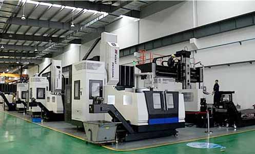
General architecture of a CNC lathe
The characteristics of CNC lathes compared to a normal universal lathe are the following:Motor and main head
This motor limits the real power of the machine and is what causes the rotating movement of the parts. Normally, current CNC lathes are equipped with a direct current motor, which acts directly on the spindle with a transmission by pulleys interposed between the location of the motor and the spindle, being unnecessary any type of transmission by gears.
These DC motors provide an almost infinite range of rotation speeds from zero to a maximum determined by the characteristics of the motor, which is programmable with the execution program of each part. Many engines incorporate two speed ranges, one for slow speeds and the other for fast speeds, in order to obtain the most favorable torque. The spindle has at its end the adaptation for the corresponding claw plates and a hole to be able to work with a bar.
The characteristics of the motor and main spindle of a CNC lathe can be the following:
Main spindle bore diameter: 100 mm
Main spindle nose: DIN 55027 No. 8 / Camclock No. 8
Morse cone No. 2
Speed range: 2
Variable spindle speed: I: 0-564 rpm II: 564-2000 rpm
Motor power: 15 kW
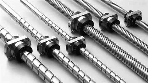
Movable bench and trolleys
In order to facilitate the rapid movement of the longitudinal and transverse carriages, the guides on which they slide are tempered and ground with a hardness of the order of 450 HB. These guides have an automated permanent greasing system.The spindles of the carriages are made of hardened and ground balls ensuring great precision in the movements, these spindles work by the principle of recirculation of balls, by means of which an endless screw has a coupling to the respective carriages. When the endless screw rotates, the carriage moves longitudinally through the guides of the bed. These screws have no play when changing direction of rotation and offer little resistance. To avoid damage from a collision of the carriage with an obstacle, they incorporate a clutch that disengages the assembly and stops the advance force.
Each car has an independent motor that can be servo motors or encoder motors that are characterized by high power and high torque at low revolutions. These motors work like a conventional AC motor, but with an encoder connected to it. The encoder controls the exact revolutions given by the motor and brakes at the exact point that marks the programmed position of the tool.
On the other hand, the structure of the bed determines the maximum dimensions of the pieces that can be machined. Example of the specifications of the bed of a CNC lathe:
Height between points: 375 mm
Diameter admitted on bed: 760 mm
Diameter over longitudinal carriage 675
Diameter admitted on cross slide. 470 mm
Z, X axis working feed. 0-10000 mm / min
Rapid movements Z, X axes 15/10 m / min
Longitudinal thrust force 9050 N
Transverse thrust force 9050 N
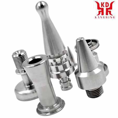
Fasteners turned on CNC lathes
|
Trolley positioning adjustment
Despite the quality of the elements that intervene in the mobility of the longitudinal and transversal carriages, there is no total guarantee of being able to achieve the position of the tools in the programmed position.To correct possible positioning errors there are two electronic systems, one of them direct and the other indirect. The direct positioning adjustment system uses a measurement ruler located in each of the bench guides, where an optical reader acts that accurately measures the position of the carriage. transferring existing deviations to the CPU (Central Processing Unit) where it is automatically reprogrammed until the correct position is achieved.
Tool holders
The CNC lathe uses a drum as a tool holder where six to twenty different tools can be located, depending on the size of the lathe, or its complexity. The tool change is controlled by the machining program, and at each change, the carriages move back to a position where the rotation and selection of the appropriate tool take place to continue the machining cycle. When the machining of the part is finished, the carriages move back to the initial position of withdrawal from the work area so that it is possible to change parts without problems. The tool-holder drum, known as a revolver, incorporates a servomotor that makes it rotate, and a hydraulic or pneumatic system that interlocks the revolver, thus giving an accuracy that is normally between 0.5 and 1 micron of a millimeter. The tools have to be adjusted to suitable coordinates in an accessory external to the lathes according to the dimensions indicated by the program. In most cases, interchangeable carbide inserts are used, which means that when the insert needs to be replaced, it is not necessary to remove the tool holder from its housing.
TOOL SETTER
This accessory allows us to facilitate the setting of the tools to be used in machining. Tool setting probes are easily installed on CNC machining centers and turning centers, allowing automated operation with the following benefits:Significant time savings with reduced machine downtime
Accurate measurement of tool length and diameter
Automatic calculation and correction of tool compensation
Elimination of manual configuration errors
Accessories and peripherals
Machine accessories are known as those equipments that, as part of it, are acquired from an external supplier, because they are universally applicable for that type of machine. For example, a car battery is an accessory to it.All machines that have built-in CNC operation require a series of accessories that in the case of a lathe are specified in the following:
CPU (Process Control Unit)
Dynamic Solid and Path Graphics
Profile editor
Input peripherals
Output peripherals
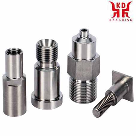
Stainless steel parts turned by CNC lathes
|
UCP (Central Processing Unit)
Main article: Central processing unitThe CPU or CPU is the calculation brain of the machine, thanks to the microprocessor it incorporates. The computing power of the machine is determined by the installed microprocessor. Any of the CPUs on the market can be installed on each machine, for example: FAGOR, FANUC, SIEMENS, etc. The normal thing is that the client chooses the characteristics of the machine he wants and then chooses the CPU that best suits him for performance, price, service, etc.
The main functions entrusted to the PCU is to develop the command and control orders that the machine must have in accordance with the machining program that the programmer has established. such as calculating the exact position that the tools must have throughout the work process, by controlling the displacement of the corresponding longitudinal and transverse carriages. You must also control the technological factors of machining, that is the spindle revolutions and the work and rapid travel feeds as well as the tool change.
On the other hand, the CPU integrates the different memories of the system, which can be EPROM, ROM, RAM and BUFFER, which serve to store the programs and act as a hard disk of any computer.
The most significant and important input peripheral is the keyboard that is installed on the machine's control panel, from where you can make corrections and modifications to the initial program, even develop an individual machining program. There are many types of input peripherals with greater or lesser complexity, which if they have to be built is resistant to aggressive environments such as those found in workshops.
The most important output peripheral is the monitor, which is where we are informed of the machining execution process and we can see all the values of each sequence. We can also control the manual movement of the trolleys and other moving parts of the machine.
Sequence number N
Sequence refers to the set of non-contradictory orders that can be given to the machine at once. They are identified by the letter N, and up to 9999 successive orders can be given on a normal lathe. If the program is not very long, they can be numbered from 10 to 10, in case it is necessary to introduce an unforeseen complementary order, so we will have N10, N20, N30, etc. or we could have, N10, N11, N20, etc.Preparatory functions G
Under the letter G accompanied by a number are grouped a wide variety of functions that allow the lathe to perform the appropriate and necessary tasks for its work.There are five basic types of preparatory functions:
Mobility functions.
Technological functions.
Conversion functions.
Special machining functions.
Modal functions.
1- Mobility functions The most important mobility functions are the following:
G00. Fast scrolling. Indicates the fastest possible movement of the tool carriage, from the reference point to the point where each tool starts work. Special care must be taken in the use of this function since the trajectory is not controlled by the user but rather the lathe acts based solely on the maximum travel speed. You never mechanize with it. It only acts at the beginning of the program, each time there is a tool change, and at the end of the program when returning to the reference point.
G01. Linear interpolation. Indicates that the tool is moving at the programmed work feedrate, allowing classic turning and facing operations as well as cone machining.
G02 Circular interpolation to the right (clockwise) It is used when it is necessary to machine spherical or radial areas with controlled speed.
G03. Circular interpolation to the left (counterclockwise). It is used when it is necessary to machine empty spherical areas, or left-hand radii.
There are other G mobility functions, less important and depending on the equipment that is installed in the machine.
2- Technological functions The technological functions are those that refer to the way of programming the spindle speed and the work advance. The spindle rotation speed can be programmed at the desired revolutions per minute, for which function G97 will be preceded, or it can be programmed to rotate at a constant cutting speed in m / min. In this case it is indicated with function G96. The same happens with the work feedrate, if you want to program the feedrate in mm / rev, the G95 function is prepended and if you want to work in mm / min the G94 function is prepended.
3- Conversion functions The most important function of this group is the one that corresponds to the zero offset to locate the part zero that is carried out by means of the G59 function. There are also functions if the dimension is in inches or millimeters. Although the one that is going to be used normally has already been preset. Another case of conversion is if it is programmed with absolute dimensions or incremental dimensions.
4- Special machining functions. The most popular of these functions is the one corresponding to a threading cycle represented by function G33. Other functions of this type are facing, drilling, tapping, reaming, etc.
5- Modal functions. In CNC programs, there are functions that, once programmed, remain active until a contrary function is programmed, or the program is terminated. These functions are called modal functions. As many functions as you want can be programmed in a block, as long as they are not incompatible with each other. For example, functions G00 and G01 cannot be programmed in a block.
Advantages and disadvantages of CNC lathes compared to conventional ones
Advantage:They allow to obtain greater precision in machining.
They allow machining more complex parts.
It can be easily changed from machining one part to another.
Operator errors are reduced.
CNC lathes are getting cheaper.
Machining times are reduced.
As disadvantages the following can be indicated:
Need to carry out a program prior to machining the first part.
High cost of tools and accessories, which implies a high investment.
Convenience of having a large occupation for the machine due to its high cost.
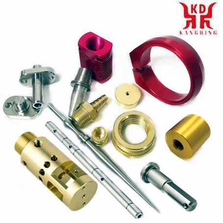
Brass parts processed by CNC lathe
|
Chip formation
The lathe has evolved so much that it is no longer just a matter of removing material at high speed, but the parameters that make up the process have to be closely controlled to ensure the final results of economy, quality and precision.The way to treat the chip becomes a complex process, where all the technological components of machining intervene, so that it can have the size and shape that does not disturb the work process. Failure to do so would rapidly build up masses of long, stringy chips in the machining area, forming tangled and uncontrollable skeins.
The shape that the chip takes is mainly due to the material being cut and can be ductile as well as brittle and brittle.
The advance with which one works and the depth of the pass are quite responsible for the shape of the chip, and when it cannot be controlled with these variables, it is necessary to resort to choosing the tool that incorporates an effective chip breaker. 16 greater efficiency than a normal lathe is faster
Dry and coolant machining
Today dry turning is completely viable and is used in many applications. There is a recent trend to carry out dry machining whenever the quality of the tool allows it. A higher cut-off temperature zone can be a positive factor in many cases.However dry machining is not suitable for all applications, especially for drilling, tapping and boring to ensure chip evacuation.
Operations, materials, parts, quality requirements, and machinery need to be carefully evaluated to identify the benefits of removing the refrigerant supply.
Technological fundamentals of turning
In turning there are six key parameters:Due to their operating mechanisms, CNC lathes allow machining conditions to be adjusted to the maximum and therefore achieve the best possible turning time.
Cutting speed (Vc). It is defined as the linear speed in the periphery of the area that is being machined. Your choice is determined by the material of the tool, the type of material of the part and the characteristics of the machine. A high cutting speed allows machining in less time but accelerates tool wear. The cutting speed is expressed in meters / minute.
Part rotation speed (N). Usually expressed in revolutions per minute. It is calculated from the cutting speed and the largest diameter of the pass being machined.
Advance (F). Defined as the penetration speed of the tool in the material. In turning it is usually expressed in mm / rev. However, in order to calculate the turning time, it is necessary to calculate the feedrate in mm / min for each pass.
Depth of pass. It is the radial distance that a tool covers in its working phase. It depends on the characteristics of the piece and the power of the lathe.
Machine power. It is expressed in kW, and it is what limits the general machining conditions, when it is not limited by other factors.
Turning time (T). It is the time it takes for all the tools to perform the machining without taking into account other issues such as possible control stops or the time to put and remove the part from the head, which can vary depending on each part and machine. It is calculated based on adding the partial times of each tool.


