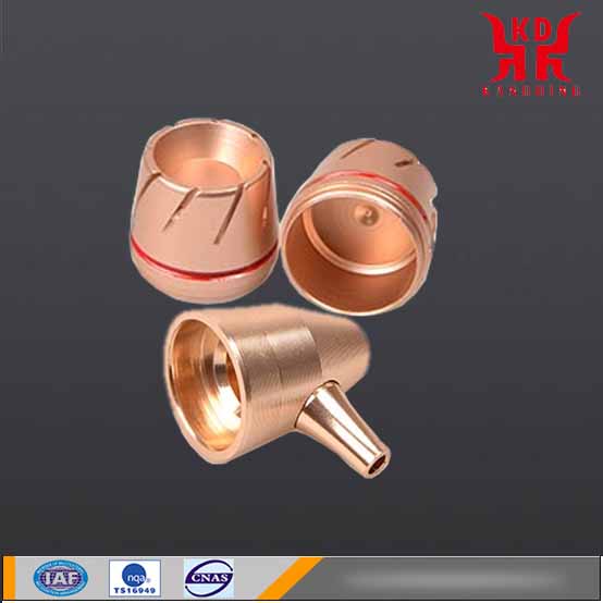
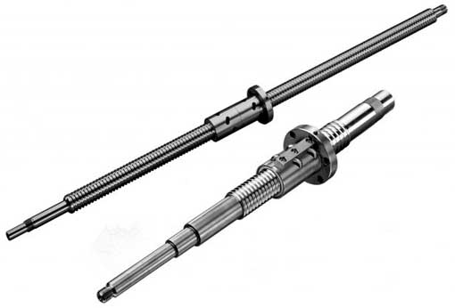
Precision turning process of large pitch threaded shaft
- PRODUCT DETAIL
Ordinary lathes sometimes experience bed saddle vibration when turning large-pitch threads forcefully. Lighter ones will cause ripples on the machined surface, and severer ones will break the knife. When cutting off, there are often knife sticking or broken tools. There are many reasons for the above problems. This phenomenon and its solution are mainly discussed through the analysis of the force of the turning tool.
1. The occurrence and cause of the problem
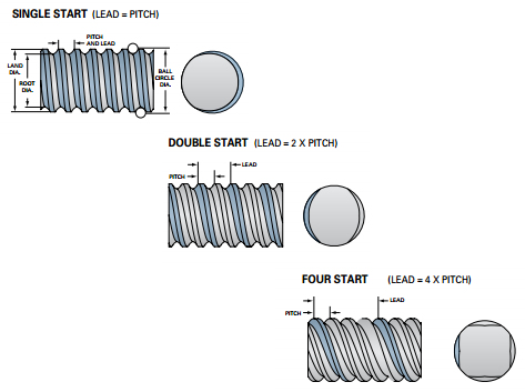
We know that when turning a thread with a small pitch, the straight-infeed cutting method is generally used (a straight-infeed is made in the direction perpendicular to the axis of the workpiece);
When turning a thread with a larger pitch, in order to reduce the cutting force, the left and right turning method is often used to turn the trapezoidal thread (by moving the small slide plate, the thread turning tool is cut with the left and right cutting edges).
When turning the thread, the movement of the saddle is realized by the movement of the opening and closing nut driven by the rotation of the long screw. There is an axial gap at the bearing of the long screw, and there is also an axial gap between the long screw and the opening and closing nut. When the right-handed worm is cut with the right main cutting edge using the left-right borrowed cutting method, the tool bears the force P given to it by the workpiece (ignoring the friction between the chips and the rake face, as shown in Figure 1). Decompose the force P into the axial component force Px and the radial component force Qiao. The axial component force Px is the same as the feed direction of the tool. The tool transmits this axial component force Px to the saddle, which pushes the saddle to move quickly and violently to the side with the gap. The result is that the tool moves back and forth, and the machined surface produces ripples or even breaks the tool. However, there is no such phenomenon when cutting with the left main cutting edge. When cutting with the left main cutting edge, the axial component force Px that the tool bears is opposite to the feed direction and moves in the direction of eliminating the gap. At this time, the saddle moves at a constant speed.
When the workpiece is cut, the movement of the middle slide is realized by the rotation of the middle slide screw driving the movement of the nut. There is an axial gap at the screw bearing, and there is also an axial gap between the screw and the nut. When cutting a workpiece on a lathe, the tool rake face (with a rake angle) bears the force P given to it by the workpiece (ignoring the friction between the chips and the rake face, as shown in Figure 2). The force P is decomposed into a force Pz and a radial component. The radial component is the same as the feed direction of the cutting tool and points to the workpiece. Push the tool into the workpiece, which will pull the middle sliding plate to move in the direction of the gap, so that the cutting knife suddenly pierces the workpiece, causing the piercing (broken) knife or the workpiece to bend.
2. Solution
When turning the thread with a larger pitch and using the left and right borrow cutting method, in addition to adjusting the relevant parameters of the lathe, the clearance between the saddle and the bed guide should also be adjusted. Make it a little tighter to increase the friction during movement and reduce the possibility of the saddle moving, but the gap should not be adjusted too tight, so it is better to shake the saddle smoothly.
Adjust the gap of the middle slide plate to minimize the gap; Adjust the tightness of the small slide plate to make it a little tighter to prevent the turning tool from shifting during turning. The extension length of the workpiece and the tool bar should be shortened as much as possible, and the left main cutting edge should be used as much as possible; When cutting with the right main cutting edge, reduce the amount of back cutting; Increase the rake angle of the right main cutting edge, and the cutting edge should be straight and sharp to reduce the axial component force Px that the tool bears. In theory, the larger the rake angle of the right main turning blade, the better.
PREV:Error compensation for turning precision parts of different materials
NEXT:CNC lathe parts processed by milling and cutting
NEXT:CNC lathe parts processed by milling and cutting