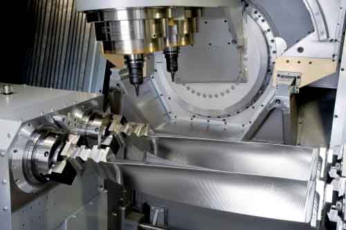
Difficulties in milling large blades of impellers

In the CNC machining of the impeller blades, the machining of large impeller blades is the most difficult. Mastering the measures to solve the processing difficulties of large blades has a very positive effect not only on the large blade itself, but also on the impeller moving blades, impeller stationary blades, guide impeller blades and impeller end blades.
The difficulties in CNC machining of large impeller blades are as follows: The shroud of the milling impeller process; Impeller blade root processing; Milling bead holes of impeller blades.
1. Since the material of the large impeller blades is forgings, the profiled part of the forgings is different from the rational wheel value, so the profiled block casted from the low melting point alloy cannot match each impeller blade. After the pressing plate is pressed, the gap between the profile line of the impeller blade and the profile cushion block deforms the processed profile line, and the size control at the shroud is unstable, resulting in scrap.
2. The processing of the impeller blade root is a difficult point in blade processing. Due to the complex profile and high precision requirements, it has always been a headache for CNC processors. In particular, the fork-shaped root of the large blade of the impeller has not only its own accuracy problem, but also the problem of deformation caused by stress release. When the fork shape is processed, the monotonicity of the shrinkage stress is caused by the disappearance of the tensile stress between each other, so that the blade root of the impeller is deformed. If the stress is great, scrapping is inevitable, and the annual loss caused by this is not small.
3. The reasons for the difficulties in CNC machining of the impeller lacing holes. A large part of it is due to the uneven deformation of the impeller blade roots, causing the radiation lines to not overlap, causing the position of the lacing hole to change, and the product produces waste. On the other hand, due to the deformation of the molding line, the gap between the molding line block and the molding line and the serious deformation cannot match.
I. Solutions to the difficulties encountered in milling the impeller blade shroud structure:
Specific operation method:
1. Put the large blades of the impeller to separate the left and right supports, pour the low melting point alloy, and lock the parts 6 and 4 together.
2. When a gap is found, the adjustment piece 3 of the piece 6 and piece 4 is loosened to make it rise to no gap, and the dead piece 4 and piece 6 are processed again.
3. Regardless of the left and right gaps, the line contact (with the profile line) can be ensured, so as to ensure the surface contact with the impeller blade. In this way, there is no need to worry about the deformation caused by the gap during processing.
4. The tooling is simple, easy to manufacture, and easy to operate. It is easy to use, especially for those large impeller blades with gaps between the molding line and the theoretical molding line, which can reduce the rejection rate (this process) by more than 80%.
II. Solutions to difficulties encountered in impeller root processing:
Before CNC machining of the impeller root, artificial aging is adopted to remove the stress in the impeller root as much as possible. This has solved part of the problem to a certain extent-stress and deformation. In the face of CNC machining itself, the operator is required. Use a dial indicator to adjust the knife, instead of using a dial indicator to adjust the workpiece, so that the 3 knives are in the correct position. It is required that the process is divided into roughing and finishing in the finishing, and the final cut is aligned, so as to avoid the error caused by the large fixed surface.
III. The solution to the difficult problem of milling the impeller lacing hole—— Correction:
Due to the solution of the CNC machining problem of the impeller root, the reuse is reduced, so that the blade root positioning is basically accurate when processing the impeller lacing hole. The remaining problem is how to solve the problem of the gap between the middle molding line and the molding line spacer. Workers generally adopt the pad method when processing. However, due to the vibration of the machine tool during processing, the cushions often fall off and become scrapped. At the same time, because this profile has a positioning function, it cannot be lifted at will, and can only be considered from the impeller itself.
Before CNC processing this process, the process should process a process-shape correction. That is to say, those mold lines that are different from the theoretical mold lines are matched with the theoretical mold lines by manpower or mechanical force. To this end, a set of calibration measuring tools is needed, that is, to check the air leakage of each profile section through the measurement of the model. Thereby measures are taken to twist it to normal conditions by human or mechanical force.
Through the above three solutions, the problem of large impeller blade processing can be basically solved, and it provides a theoretical basis for the processing of other types of impeller blades, and has accumulated valuable experience.


