CNC machining plan for typical precision metal parts
The development of three-dimensional design software provides conditions for low-cost, short-period, and design of positioning fixtures. And it can simulate CNC machining parts for verification. Figure 1 shows a typical metal part with an angle of 45° to the YZ and ZX planes:
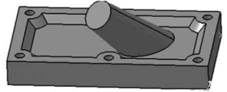
figure 1 Choosing the plan of parts CNC machining
This kind of parts with special spatial structure generally has 2 kinds of CNC machining methods:
① Improve the performance of the machine tool, that is, increase the original 2.5-axis or 3-axis CNC machine tool to more than 5 axes;
② Design a suitable positioning fixture and use existing equipment for processing.
Considering the processing cost, the second option is obviously a more ideal choice. The following is to design a positioning fixture for this part, and use CATIA software to perform solid modeling, assembly, interference detection, and accuracy analysis of each component of the fixture. Import the designed fixture into the CNC machining module for virtual machining to check the feasibility and correctness of the design.
Design and 3D modeling of positioning fixture
Considering the characteristics of the processed parts, ensuring the accuracy of processing, and in order to improve the scope of application of the fixture, the positioning fixture is designed as a modular combined fixture, as shown in Figure 2. The fixture is mainly composed of 4 parts: positioning bracket, positioning plate, guide module and positioning clamp. The positioning bracket is the cornerstone of the entire fixture, which directly determines the inclination of positioning, and other parts are also installed on it.
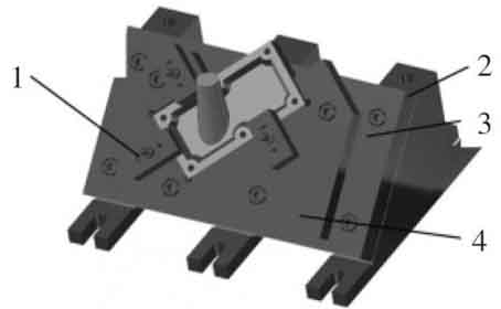
Figure 2 Three-dimensional solid model of positioning fixture
1. Positioning clip
2. Positioning bracket
3. Positioning plate
4. Guidance Module
The positioning plate is used to install the guide module to the positioning bracket, and when the size and shape of the base surface of the workpiece to be processed with an inclination of 45° change, only the structure and size of the guide module need to be changed. Choosing a suitable position on the positioning plate for fixing makes the positioning clamp applicable to a wider range. The design of the guide module and the positioning clamp should be based on the structure and shape of the processed part, so that it matches the outer surface of the part to be processed, and the height should be the same to facilitate the installation of the positioning clamp. The positioning clamp is generally designed and installed with three-point positioning, and cooperates with the positioning plate to realize the limitation of 6 degrees of freedom of the parts to be processed.
Static interference inspection of positioning fixture
In order to ensure that the components of the designed fixture can be processed and assembled, and can achieve its positioning function, interference detection must be performed on the fixture.
Static interference analysis includes the interference between the fixture units and the interference between the fixture and the workpiece. Each fixture is composed of several units, and the completion includes positioning and clamping. Due to the limited space and the complex structure of each unit, and the design of the fixture is generally designed layer by layer, it is difficult to control the margin of the space and easy to interfere. In addition, the shape of the workpiece is complex, and the workpiece may not be installed correctly due to the location or structure of the fixture unit.
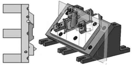
Figure 3 Schematic diagram of static interference detection
Under the "DMUSpaceAnalysis" module in CATIA, perform static interference analysis on the fixture, and use the collision detection "CheckClash" and the section tool "SectioningDefinition" to detect the fixture.
Dynamic interference analysis
Use the "DUMFitting" module provided by CATIA to inspect the assembled products. It can record the transfer path of parts during assembly, analyze the dynamic space required by moving parts when assembling parts, and detect the interference between parts. First switch the "assembly design" to the "DUMFitting" module, and give each assembly path according to the fixture assembly, which includes the transfer distance information of each component. The purpose is to be able to obtain the specific interference position and depth when the interference occurs, then establish the assembly simulation in order, and finally open the "collision" analysis. The analysis result is shown in Figure 4.
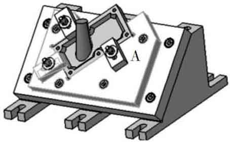
Figure 4 Dynamic collision detection
Area A shown in Figure 4 is the location where interference occurs, and its specific display is shown in Figure 5. Interference occurs between the positioning clamp and the guide module. Through the analysis of the interference information, it is concluded that the positioning clip collides with the assembly path of the guide module during the assembly process. For interference appears, make the following changes to fixture: Under the premise of keeping the positioning point and clamping point unchanged, change the spatial position or some size parameters of other parts in the unit.
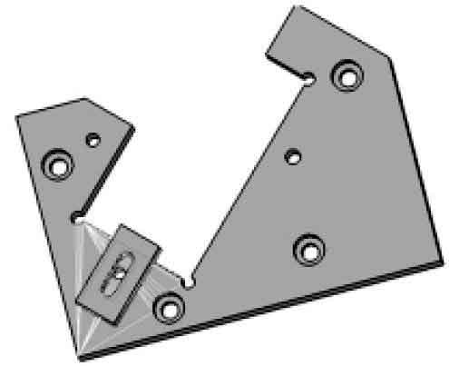
Figure 5, the area where interference occurs
CNC simulation processing
Use the "processing" module provided by CATIA to perform CNC machining on the workpiece to check whether the tool collides with the fixture when processing the workpiece, so as to verify the feasibility of CNC machining. In order to be able to observe whether the collision occurs intuitively, this article chooses to process the outer contour of the draft cylinder with spatial inclination in the workpiece. First, switch the assembled fixture to "Surface Machining" under the "Machining" module to perform "Contour driven" (contour driven finishing) on the outer surface of the machined part;
Then select the machining area as the part to be machined in the pop-up dialog box, and select the appropriate tool path parameters, including the selection of the driving guide line, the appropriate tool parameters and the tool exit route;
Finally, CNC simulation processing is performed to generate the tool path line, as shown in Figure 6.
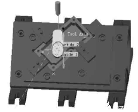
Figure 6, the generated tool path line
Total positioning error of fixture:
(Where δK= process size tolerance of the workpiece)
The above cases can effectively reduce costs and shorten the design and production cycle through the use of CATIA's three-dimensional virtual design capabilities, the design and functional testing of positioning fixtures; In the entire design composition, the computer completes the process from design to assembly to simulation processing on CNC machine tools, including static and dynamic interference analysis. This is unmatched by traditional design methods, and it is also an inevitable trend in the development of modern fixture industry.
figure 1 Choosing the plan of parts CNC machining
① Improve the performance of the machine tool, that is, increase the original 2.5-axis or 3-axis CNC machine tool to more than 5 axes;
② Design a suitable positioning fixture and use existing equipment for processing.
Considering the processing cost, the second option is obviously a more ideal choice. The following is to design a positioning fixture for this part, and use CATIA software to perform solid modeling, assembly, interference detection, and accuracy analysis of each component of the fixture. Import the designed fixture into the CNC machining module for virtual machining to check the feasibility and correctness of the design.
Design and 3D modeling of positioning fixture
Considering the characteristics of the processed parts, ensuring the accuracy of processing, and in order to improve the scope of application of the fixture, the positioning fixture is designed as a modular combined fixture, as shown in Figure 2. The fixture is mainly composed of 4 parts: positioning bracket, positioning plate, guide module and positioning clamp. The positioning bracket is the cornerstone of the entire fixture, which directly determines the inclination of positioning, and other parts are also installed on it.
Figure 2 Three-dimensional solid model of positioning fixture
2. Positioning bracket
3. Positioning plate
4. Guidance Module
The positioning plate is used to install the guide module to the positioning bracket, and when the size and shape of the base surface of the workpiece to be processed with an inclination of 45° change, only the structure and size of the guide module need to be changed. Choosing a suitable position on the positioning plate for fixing makes the positioning clamp applicable to a wider range. The design of the guide module and the positioning clamp should be based on the structure and shape of the processed part, so that it matches the outer surface of the part to be processed, and the height should be the same to facilitate the installation of the positioning clamp. The positioning clamp is generally designed and installed with three-point positioning, and cooperates with the positioning plate to realize the limitation of 6 degrees of freedom of the parts to be processed.
Static interference inspection of positioning fixture
In order to ensure that the components of the designed fixture can be processed and assembled, and can achieve its positioning function, interference detection must be performed on the fixture.
Static interference analysis includes the interference between the fixture units and the interference between the fixture and the workpiece. Each fixture is composed of several units, and the completion includes positioning and clamping. Due to the limited space and the complex structure of each unit, and the design of the fixture is generally designed layer by layer, it is difficult to control the margin of the space and easy to interfere. In addition, the shape of the workpiece is complex, and the workpiece may not be installed correctly due to the location or structure of the fixture unit.
Figure 3 Schematic diagram of static interference detection
Under the "DMUSpaceAnalysis" module in CATIA, perform static interference analysis on the fixture, and use the collision detection "CheckClash" and the section tool "SectioningDefinition" to detect the fixture.
Dynamic interference analysis
Use the "DUMFitting" module provided by CATIA to inspect the assembled products. It can record the transfer path of parts during assembly, analyze the dynamic space required by moving parts when assembling parts, and detect the interference between parts. First switch the "assembly design" to the "DUMFitting" module, and give each assembly path according to the fixture assembly, which includes the transfer distance information of each component. The purpose is to be able to obtain the specific interference position and depth when the interference occurs, then establish the assembly simulation in order, and finally open the "collision" analysis. The analysis result is shown in Figure 4.
Figure 4 Dynamic collision detection
Area A shown in Figure 4 is the location where interference occurs, and its specific display is shown in Figure 5. Interference occurs between the positioning clamp and the guide module. Through the analysis of the interference information, it is concluded that the positioning clip collides with the assembly path of the guide module during the assembly process. For interference appears, make the following changes to fixture: Under the premise of keeping the positioning point and clamping point unchanged, change the spatial position or some size parameters of other parts in the unit.
Figure 5, the area where interference occurs
Use the "processing" module provided by CATIA to perform CNC machining on the workpiece to check whether the tool collides with the fixture when processing the workpiece, so as to verify the feasibility of CNC machining. In order to be able to observe whether the collision occurs intuitively, this article chooses to process the outer contour of the draft cylinder with spatial inclination in the workpiece. First, switch the assembled fixture to "Surface Machining" under the "Machining" module to perform "Contour driven" (contour driven finishing) on the outer surface of the machined part;
Then select the machining area as the part to be machined in the pop-up dialog box, and select the appropriate tool path parameters, including the selection of the driving guide line, the appropriate tool parameters and the tool exit route;
Finally, CNC simulation processing is performed to generate the tool path line, as shown in Figure 6.
Figure 6, the generated tool path line
Total positioning error of fixture:
(Where δK= process size tolerance of the workpiece)
The above cases can effectively reduce costs and shorten the design and production cycle through the use of CATIA's three-dimensional virtual design capabilities, the design and functional testing of positioning fixtures; In the entire design composition, the computer completes the process from design to assembly to simulation processing on CNC machine tools, including static and dynamic interference analysis. This is unmatched by traditional design methods, and it is also an inevitable trend in the development of modern fixture industry.


