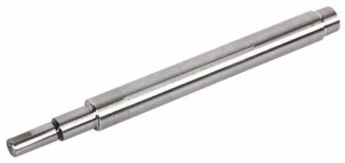
CNC machining of rotor shaft
What is a rotor shaft?
The rotor shaft is a relatively important shaft component in mechanical transmission. Due to the high quality requirements of the rotor shaft, its CNC machining is very difficult, so according to the existing machining technology, generally experienced technicians are used for manual operation.
The process flow of rotor shaft processing is as follows: Cutting and forming blanks → Wear and tear → Rough turning A-axis and B-axis section → Tempering → Fine grinding → Finish turning A-axis and B-axis section → Taper
High-frequency heat treatment and tempering of the tapered part and the small shaft part → Gear hobbing → High-frequency heat treatment and tempering of the formed teeth to form semi-finished products → Grind semi-finished products in third gear → Rushing →Anti-rust treatment and inspection.
Most of our factory adopts automated processing methods, with high production efficiency and good product consistency. The produced and processed rotor shafts are of high quality, and the product accuracy is very consistent.
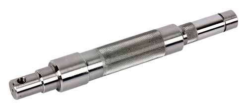
The utility model discloses a rotor shaft, which comprises a shaft body and a shaft handle, and the shaft body and the shaft handle are detachably connected. A fan-shaped convex block is provided at one end of the shaft opposite to the shaft body, and a plurality of convex blocks are evenly arranged along the circumferential direction of the shaft shaft. The convex blocks form a uniform fan annular gap along the circumferential direction between each other, and a plurality of convex blocks are arranged with a uniform gap along the axial direction of the shaft handle. One end of the shaft body opposite to the shaft handle is provided with a butting hole matching the shaft handle, and the inner wall of the butting hole is provided with a clamping groove matching the shape of the convex block. The convex block and the butting groove realize the clamping connection during the process of rotating the shaft handle. A locking mechanism for locking the circumferential movement of the shaft is also provided between the shaft body and the shaft handle, and it can be seen that the general installation method of the shaft shaft through threaded connection is avoided. The utility model only needs the axial and circumferential locking to realize the installation of the shaft handle and the shaft body. And in the subsequent work, it will not be like a normal shaft shank connected by a thread, because the shaft body and the shaft shank will loosen due to vibration.


