CNC boring processing
CNC boring is the further processing of holes that have been drilled, cast or forged with a boring tool. It can be carried out on a lathe, boring machine or milling machine. CNC boring is one of the commonly used hole processing methods, which can be divided into rough boring, semi-precision boring and fine boring. The dimensional tolerance level of rough boring is IT13~IT12, and the surface roughness value is Ra12.5~6.3μm; The dimensional tolerance grade of semi-precision boring is IT10~IT9, and the surface roughness value is Ra6.3~3.2μm; The dimensional tolerance grade of fine boring is IT8~IT7, and the surface roughness value is Ra1.6~0.8μm.
1. Turning hole of lathe
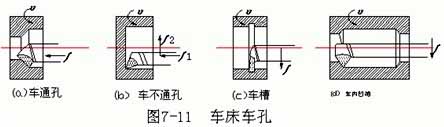
The turning hole of the lathe is shown in Figure 7-11. For turning impervious holes or holes with right-angle steps (Figure 7-11b), the turning tool can perform longitudinal feed motion first. When cutting to the end of the hole, the turning tool changes to a transverse feed movement, and then the inner end face is processed. In this way, the inner end surface can be well connected with the hole wall. Turn the groove of the inner hole (Figure 7-11d), extend the turning tool into the hole, do the horizontal feed first, cut to the required depth, and then do the longitudinal feed movement.
The turning hole on the lathe is the rotation of the workpiece and the movement of the turning tool. The size of the aperture can be controlled by the cutting depth and the number of passes of the turning tool, and the operation is more convenient.
The turning holes of the lathe are mostly used to process the holes of the disc sleeve and small bracket parts.
 2. Boring machine boring processing
There are three main methods for boring processing on a boring machine:
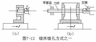
(1) The spindle of the boring machine drives the tool bar and the boring tool to rotate, and the worktable drives the workpiece to make a longitudinal feed movement, as shown in Figure 7-12. The bore diameter boring in this way is generally less than about 120mm. Figure 7-12a shows the overhanging tool bar, which should not be extended too long to avoid excessive bending and deformation. Generally used to boring holes with a small depth. The boring bar shown in Figure 7-12b is longer and is used to boring coaxial holes with a long distance between the two walls of the box. In order to increase the rigidity of the boring tool bar, the other end of the tool bar is supported in the guide sleeve seat of the rear column of the boring machine.
(2) The spindle of the boring machine drives the tool bar and the boring tool to rotate and perform longitudinal feed motion, as shown in Figure 7-13. In this way, the length of the main shaft overhang continues to increase, and the rigidity decreases accordingly. Generally only used for boring short holes.
For the above two boring methods, the size and tolerance of the aperture should be ensured by adjusting the length of the cutter head, as shown in Figure 7-14. Adjustment, trial boring and measurement are required, and formal boring can only be carried out after the aperture is qualified. The technical requirements for its operation are relatively high.
(3) The flat rotating disc of the boring machine drives the boring cutter to rotate, and the worktable drives the workpiece to make longitudinal feed motion.
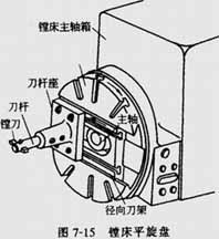
As shown in Figure 7-15, the flat-rotating plate of the boring machine can move up and down with the headstock, and can rotate itself. The radial tool post in the middle part can do radial feed movement, and can also be in any position required.
As shown in Figure 7-16a, use the radial tool post to make the boring tool in an eccentric position to boring large holes. This boring method is often used for holes over Φ200mm, but the holes should not be too long. Figure 7-16b, for boring the inner groove, the flat rotating disk drives the boring tool to rotate, and the radial tool post drives the boring tool to make a continuous radial feed movement. If the tip of the tool is extended from the end of the tool bar, the end face of the hole can also be bored.
The boring machine is mainly used for boring the supporting holes, inner grooves and the end faces of the large and medium-sized brackets or boxes; the boring machine can also be used for drilling, reaming, milling grooves and milling planes.
3. Boring technology of milling machine
Boring on a horizontal milling machine is the same as that shown in Figure 7-12a. The boring bar is installed in the spindle taper hole of the horizontal milling machine for rotating movement, and the workpiece is installed on the worktable for lateral feed movement.
4. Floating boring hole
As mentioned above, lathes, boring machines and milling machines mostly use single-edged boring tools. In batch or mass production, the floating boring tool can be used for finishing the holes with large diameter (>Φ80mm), long hole depth and high precision.
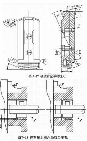
The adjustable floating boring block is shown in Figure 7-17. When adjusting, loosen the two screws 2 and turn the screw 3 to adjust the radial position of the cutter block 1 to make it conform to the diameter and tolerance of the boring hole. The floating boring tool turns the workpiece on the lathe as shown in Figure 7-18. When working, the tool bar is fixed on the square tool holder, and the floating boring tool block is installed in the rectangular hole of the tool bar. Relying on the balance of the radial cutting forces of the two edges to automatically center, which can eliminate the hole diameter error caused by the installation error of the tool block on the tool bar.
Floating boring is essentially equivalent to reaming, and its machining allowance, achievable dimensional accuracy and surface roughness values are similar to those of reaming. The advantages of floating boring are that it is easy and stable to ensure the processing quality, simple operation, and high productivity. However, the position error of the original hole cannot be corrected, so the position accuracy of the hole should be guaranteed in the previous process.
1. Turning hole of lathe
The turning hole of the lathe is shown in Figure 7-11. For turning impervious holes or holes with right-angle steps (Figure 7-11b), the turning tool can perform longitudinal feed motion first. When cutting to the end of the hole, the turning tool changes to a transverse feed movement, and then the inner end face is processed. In this way, the inner end surface can be well connected with the hole wall. Turn the groove of the inner hole (Figure 7-11d), extend the turning tool into the hole, do the horizontal feed first, cut to the required depth, and then do the longitudinal feed movement.
The turning hole on the lathe is the rotation of the workpiece and the movement of the turning tool. The size of the aperture can be controlled by the cutting depth and the number of passes of the turning tool, and the operation is more convenient.
The turning holes of the lathe are mostly used to process the holes of the disc sleeve and small bracket parts.
There are three main methods for boring processing on a boring machine:
(1) The spindle of the boring machine drives the tool bar and the boring tool to rotate, and the worktable drives the workpiece to make a longitudinal feed movement, as shown in Figure 7-12. The bore diameter boring in this way is generally less than about 120mm. Figure 7-12a shows the overhanging tool bar, which should not be extended too long to avoid excessive bending and deformation. Generally used to boring holes with a small depth. The boring bar shown in Figure 7-12b is longer and is used to boring coaxial holes with a long distance between the two walls of the box. In order to increase the rigidity of the boring tool bar, the other end of the tool bar is supported in the guide sleeve seat of the rear column of the boring machine.
(2) The spindle of the boring machine drives the tool bar and the boring tool to rotate and perform longitudinal feed motion, as shown in Figure 7-13. In this way, the length of the main shaft overhang continues to increase, and the rigidity decreases accordingly. Generally only used for boring short holes.
For the above two boring methods, the size and tolerance of the aperture should be ensured by adjusting the length of the cutter head, as shown in Figure 7-14. Adjustment, trial boring and measurement are required, and formal boring can only be carried out after the aperture is qualified. The technical requirements for its operation are relatively high.
(3) The flat rotating disc of the boring machine drives the boring cutter to rotate, and the worktable drives the workpiece to make longitudinal feed motion.
As shown in Figure 7-15, the flat-rotating plate of the boring machine can move up and down with the headstock, and can rotate itself. The radial tool post in the middle part can do radial feed movement, and can also be in any position required.
As shown in Figure 7-16a, use the radial tool post to make the boring tool in an eccentric position to boring large holes. This boring method is often used for holes over Φ200mm, but the holes should not be too long. Figure 7-16b, for boring the inner groove, the flat rotating disk drives the boring tool to rotate, and the radial tool post drives the boring tool to make a continuous radial feed movement. If the tip of the tool is extended from the end of the tool bar, the end face of the hole can also be bored.
The boring machine is mainly used for boring the supporting holes, inner grooves and the end faces of the large and medium-sized brackets or boxes; the boring machine can also be used for drilling, reaming, milling grooves and milling planes.
3. Boring technology of milling machine
Boring on a horizontal milling machine is the same as that shown in Figure 7-12a. The boring bar is installed in the spindle taper hole of the horizontal milling machine for rotating movement, and the workpiece is installed on the worktable for lateral feed movement.
4. Floating boring hole
As mentioned above, lathes, boring machines and milling machines mostly use single-edged boring tools. In batch or mass production, the floating boring tool can be used for finishing the holes with large diameter (>Φ80mm), long hole depth and high precision.
The adjustable floating boring block is shown in Figure 7-17. When adjusting, loosen the two screws 2 and turn the screw 3 to adjust the radial position of the cutter block 1 to make it conform to the diameter and tolerance of the boring hole. The floating boring tool turns the workpiece on the lathe as shown in Figure 7-18. When working, the tool bar is fixed on the square tool holder, and the floating boring tool block is installed in the rectangular hole of the tool bar. Relying on the balance of the radial cutting forces of the two edges to automatically center, which can eliminate the hole diameter error caused by the installation error of the tool block on the tool bar.
Floating boring is essentially equivalent to reaming, and its machining allowance, achievable dimensional accuracy and surface roughness values are similar to those of reaming. The advantages of floating boring are that it is easy and stable to ensure the processing quality, simple operation, and high productivity. However, the position error of the original hole cannot be corrected, so the position accuracy of the hole should be guaranteed in the previous process.


