Dimensions of machined parts drawings: standard tolerances and basic deviations, surface roughness, accuracy, flatness, position, parallelism, coaxiality, etc.
| Shape and position tolerance | Position degree | Parallelism | Concentricity | Verticality | Full jump accuracy | Symmetry | Flatness | Cylindricity | Roundness | Roughness |
| symbol | ||||||||||
| measurement accuracy | 0.001 | 0.001 | 0.001 | 0.001 | 0.001 | 0.001 | 0.001 | 0.001 | 0.001 | Ra0.01 |
| Machining accuracy | 0.03 | 0.005 | 0.005 | 0.01 | 0.01 | 0.01 | 0.002 | 0.01 | 0.005 | Ra0.04 |

Symbol of surface roughness of parts
The concept of part surface roughness
There are peaks and valleys with small spacing on the surface of the part, and the micro-geometric characteristics formed by it are called surface roughness. When CNC machining parts, it is formed due to the tool marks left by the tool on the surface of the part and the plastic deformation of the surface metal when CNC cutting and splitting.
The surface roughness of parts is also a technical index for evaluating the surface quality of parts. It has an impact on the matching properties, working accuracy, wear resistance, corrosion resistance, sealing, appearance, etc. of the parts.
The code, symbol and mark of surface roughness
GB/T 131-1993 specifies the surface roughness code and its notation. The symbols on the drawing that indicate the surface roughness of parts are shown in the table below.
The evaluation parameters of surface roughness of parts are:
1) The arithmetic mean deviation of contour (Ra)
Within the sampling length, the arithmetic mean of the absolute value of the contour offset. The value of Ra and the sampling length l. See table.
2) Maximum profile height (Rz)
The distance between the top line of the contour peak and the bottom line of the contour peak within the sampling length.
Remarks: The Ra parameter is preferred when using it.
Marking requirements for surface roughness
1) Example of code labeling of surface roughness
When the surface roughness height parameters Ra, Rz, Ry are marked with numerical values in the code, except that the parameter code Ra can be omitted. The other parameters need to be marked with the corresponding parameter code Rz or Ry before the parameter value. See the table for labeling examples.
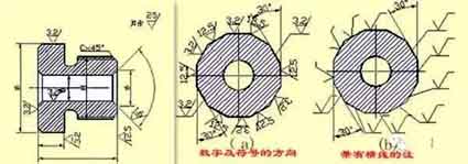
2) The method of marking the numbers and symbols in the surface roughness of the surface roughness
Marking method of surface roughness symbols on drawings
1) The surface roughness code (symbol) should generally be noted on the visible contour line, the size boundary line or their extension line, and the tip of the symbol must point to the surface from the outside of the material.
2) The direction of the numbers and symbols in the surface roughness code must be marked as required.
Labeling example of surface roughness
On the same drawing, each surface is generally marked with a code (symbol) only once, and as close to the relevant dimension line as possible. When the space is narrow or it is inconvenient to label, it can lead to the label. When all the surfaces of the parts have the same surface roughness requirements, they can be uniformly marked on the upper right corner of the drawing. When most of the surfaces of the parts have the same surface roughness requirements, the most used code (symbol) can be marked on the upper right corner of the drawing at the same time, and the word “the rest” shall be added. The height of the uniformly marked surface roughness code (symbol) and explanatory text should be 1.4 times that of the drawing mark.
Continuous surfaces on parts, surfaces of repeated elements (such as holes, teeth, grooves, etc.), and the same surface that is not continuous with thin solid lines. The surface roughness code (symbol) number is only noted once.
When there are different surface roughness requirements on the same surface, thin solid lines should be used to draw the dividing line, and the corresponding surface roughness code and size should be noted.
When the tooth (tooth) shape is not drawn on the working surface of gears, threads, etc., the surface roughness code (symbol) notation method.
The working surface of the center hole, the working surface of the keyway, the surface roughness code of the chamfer, and the rounded corner can be simplified and marked.
When the parts need to be partially heat-treated or partially plated (coated), thick dotted lines should be used to draw the range and mark the corresponding dimensions. It can also be written on the horizontal line of the long side of the surface roughness symbol.

Numbers and symbols in surface roughness

Standard tolerance and basic deviation
5. Standard tolerance and basic deviation
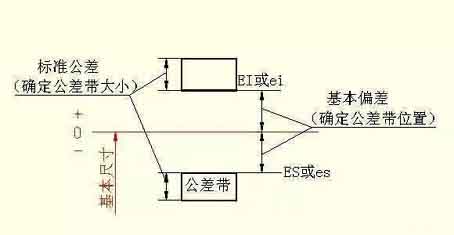
In order to facilitate production, realize the interchangeability of parts and meet different usage requirements, the national standard “Limits and Fits” stipulates that the tolerance zone is composed of two elements: standard tolerance and basic deviation. The standard tolerance determines the size of the tolerance zone, and the basic deviation determines the location of the tolerance zone.
1) Standard tolerance (IT)
El valor de la tolerancia estándar está determinado por el tamaño básico y la clase de tolerancia. El nivel de tolerancia es una marca para determinar la precisión del tamaño. La tolerancia estándar se divide en 20 niveles, a saber, IT01, IT0, IT1, …, IT18. La precisión de su tamaño disminuye de IT01 a IT18. Los valores específicos de las tolerancias estándar se pueden encontrar en las normas correspondientes.

Basic deviation of CNC machining
2) Desviación básica
La desviación básica se refiere a la desviación superior o inferior de la zona de tolerancia con respecto a la posición de la línea cero en el límite y ajuste estándar, y generalmente se refiere a la desviación cerca de la línea cero. Cuando la zona de tolerancia está por encima de la línea cero, la desviación básica es la desviación más baja; Por el contrario, es la desviación superior. Hay 28 desviaciones básicas en total, y los nombres de los códigos se expresan en letras latinas, con mayúsculas como agujero y minúsculas como eje.
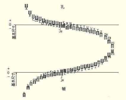
It can be seen from the basic deviation series diagram:
The basic deviation A~H of the hole and the basic deviation k~zc of the shaft are the lower deviation; The basic deviation K~ZC of the hole and the basic deviation a~h of the shaft are the upper deviation; The tolerance zones of JS and js are symmetrically distributed on both sides of the zero line, and the upper and lower deviations of the hole and shaft are +IT/2 and -IT/2 respectively. The basic deviation series diagram only shows the position of the tolerance zone, not the size of the tolerance. Therefore, one end of the tolerance zone is an opening, and the other end of the opening is defined by a standard tolerance.
The basic deviation and standard tolerance, according to the definition of dimensional tolerance, have the following calculation formulas:
ES=EI+IT or EI=ES-IT
ei=es-IT or es=ei+IT
The tolerance zone code of the hole and shaft is composed of the basic deviation code and the tolerance zone grade code.
 English
 العربية
 中文(漢字)
 Čeština
 Dansk
Dansk Nederlands
 Suomi
Suomi Français
 Deutsch
 Italiano
 日本語
日本語 ಕನ್ನಡ
ಕನ್ನಡ 한국어
한국어 Português
 Русский
 Slovenčina
 Español
 Svenska
 Türkçe

