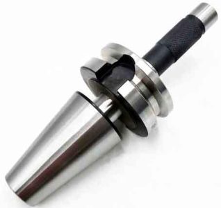
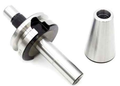
Calibrating tools for CNC machine tools is an important skill in machining. The accuracy of the tool setting determines the machining accuracy of the part, and the efficiency of the calibration tool directly affects the machining efficiency of the part. Tool setting is very important to machine tool processing operations.
After the CNC lathe is turned on, the zero return (reference point) operation must be performed. Its purpose is to establish a unified reference for position measurement, control, and display of the CNC lathe, that is, the tool returns to the origin of the machine tool. The origin of the machine tool is usually at the maximum positive stroke of the tool, and its position is determined by the machine tool position sensor. After the machine tool returns to zero, the distance between the position of the tool (tool tip) and the machine origin is fixed. Therefore, in order to facilitate tool calibration and processing, the position of the tool tip after the machine zero return can be regarded as the machine origin.

Tool calibration method for CNC machining
Calibrating the tool is the process of establishing the workpiece coordinate system in the machine coordinate system of the CNC machine tool, and making the origin of the workpiece coordinate system coincide with the programming origin. Measure the distance between the tool tip programming point in the machine tool coordinate system and the machining origin in the X and Z directions by trial cutting or non-contact methods, and set the value to the machine parameters. Through the program call, the coordinate system of the workpiece is established. The absolute coordinate value of the base point in the program is based on the origin of the established workpiece coordinate system, and the contour of the part is processed.
There are many ways to calibrate the knife on the CNC lathe, and the trial cutting method is commonly used in the work. The following introduces FANUC-0I CNC lathe commonly used calibration tool method.
1. Measure and input tool offset method
1) Trial cut the outer circle of the workpiece with the selected tool, and align the tool in the X direction. In manual operation mode, try cutting the outer circle, keep the X direction unchanged, and the tool exits along the Z axis. Use a vernier caliper to measure the diameter value α of the cut outer circle, and click the “OFFSETSETING” button to enter the shape compensation parameter setting interface. Move the cursor to the X position of tool compensation, enter Xα, and click the soft key [Measure]. The numerical control system automatically calculates the coordinates of the current tool tip in the X direction in the machine tool coordinate system, and the X direction completes the calibration of the tool.

Machine tool calibration
2) Use the selected tool to cut the end face and calibrate the tool in Z direction. In manual operation mode, the tool cuts the end face of the workpiece to the center. Then the Z direction remains motionless, and the tool exits in the X direction. Enter the shape compensation parameter setting interface, move the cursor to the corresponding position of the tool compensation Z coordinate, enter Z0, press the [Measure] soft key, the corresponding tool offset is automatically input, and the tool setting is completed. This method is to set the machining origin on the center of the right end of the workpiece, which is a common method for general shaft parts. If it is a left-right symmetrical part, the machining origin needs to be set at the symmetrical center of the workpiece, then input Zβ, β is half of the axial length of the part.
Then enter the value of the tool nose arc radius R and the tool position number T according to the geometrical size and installation position of the tool, for example:
For the No. 1 tool, the radius of the tool tip arc is R=0.8mm, move the cursor to the position corresponding to No. 1 tool below R, key in 0.8, enter the tool position number at the corresponding position of T, and press “INPUT” to input, then it can be used for processing.
2. Z-direction calibration knife after the workpiece is turned around
After the workpiece is turned around, the machining must ensure the overall length of the part after machining. Therefore, the knife must be calibrated twice. The X direction is the same as the previous tool setting method. The steps of Z-direction tool setting are as follows:
Cut the end face of the workpiece to the center, keep the Z direction still, press the X forward button, and the tool exits. Measure the total length of the workpiece blank in Z direction as Z1, the required total length of the workpiece is Z, and the length difference is ∆=Z1-Z. Before executing the program, you must first set the O point as the machining origin (see Figure 1), and enter the shape compensation parameter setting interface. Move the cursor to the Z coordinate position, enter Z∆, (∆ is the Z coordinate value of the current position of the tool tip in the newly created workpiece coordinates), press the [Measure] soft key, and the corresponding tool offset is automatically input.
3. G92 sets the workpiece coordinate system
1) Use an external turning tool to first try turning the external circle. After measuring the diameter of the outer circle, the tool is withdrawn in the positive direction of the Z axis, and the spindle stops. Note down the absolute coordinate value X1 of the tool in the machine tool coordinate system at this time, and measure the outer circle diameter D at the same time.
2) Cut the end face to the center, X does not move, and exit along the Z direction. Write down the absolute coordinate value Z1 of the tool in the machine tool coordinate system at this time;
3) Select the starting point. The starting point should be selected outside the workpiece. If the starting point is set at 50mm in the X direction and 50mm in the Z direction from the center of the right end face. Then the position of the starting point in the machine coordinate system X = X1-D+100.0 (diameter programming), Z=Z1+50.0;
4) Adjust the tool to reach the point. Before executing the program with the workpiece coordinate system set by G92, the tool must be adjusted to the up-point position. Methods as below:
First move the tool to the position close to the starting point in the manual state, and then adjust the magnification by the handwheel to reach the precise position;
5) At this time, the starting point of the program must be: G92 X100.0 Z50.0
Description:
(1) The tool must be calibrated before executing this instruction, and the tool tip must be placed at the starting point position required by the program by adjusting the machine tool;
(2) Executing the G92 command will not cause any movement of the machine tool. Just let the system replace the old coordinate value with the new coordinate value, thereby establishing a new coordinate system.
When using the trial cutting method to verify the tool, the error of the verification tool mainly comes from the measurement error after the trial cutting of the workpiece and the error caused by the visual inspection during the operation. The main measures to reduce the tool setting error are: The attitude must be rigorous, the operation must be careful, and the reading must be accurate; When processing, consider the influence of the machine tool’s repeated positioning accuracy on the tool setting accuracy and the influence of the installation height of the tool location point on the tool setting accuracy; After tool setting, the tool compensation value should be corrected according to the error between the actual size of the part processed by the tool and the programmed size.
Numerical control lathes have a variety of control systems. The tool calibration methods include manual calibration, calibration of external calibrator of the machine tool, and automatic calibration. Manual tool setting adopts the mode of “trial cutting-measurement-adjustment”, which is simple and economical, takes a long time in the machine tool, and has a large error. Using the calibrator for tool setting can automatically calculate the difference between the length of each knife and the standard knife, and store it in the system. When processing other parts, only the standard knife is needed, which greatly saves work assistance time. In addition, the use of a tool setting instrument for tool setting can eliminate errors during measurement and greatly improve the accuracy of tool setting. Automatic tool setting is realized by the tool tip detection system. The tool tip approaches the touch sensor at a set speed. When the tip of the tool touches the sensor and sends a signal, the CNC system immediately records the coordinate value at that moment and automatically corrects the tool compensation value. Although the principle of inputting parameters of external tool setting instrument and automatic tool setting is similar to that of manual tool setting, the principle and method of measurement are different, the degree of automation is high, and the work efficiency is improved.
Each tool calibration method has its own advantages and disadvantages, and operators can use them flexibly according to their actual needs. In this way, the entire tool setting work is simple, and the processing quality can be ensured, and the auxiliary time can be greatly saved, and the production efficiency can be effectively improved.
 English
 العربية
 中文(漢字)
 Čeština
 Dansk
Dansk Nederlands
 Suomi
Suomi Français
 Deutsch
 Italiano
 日本語
日本語 ಕನ್ನಡ
ಕನ್ನಡ 한국어
한국어 Português
 Русский
 Slovenčina
 Español
 Svenska
 Türkçe

