Tool path design for 5-axis CNC machining
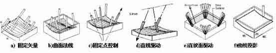
Numerical control processing of spatial curved surface involves a lot of content, especially when it comes to 5-axis processing. The five-axis machining involves key technologies such as machining guide surface, interference surface, trajectory restriction area, tool advance and retreat, and tool axis vector control. The basis of four-axis and five-axis machining is to understand the vector change of the tool axis. One of the key technologies for 4-axis and 5-axis machining is how the vector of the tool axis (the axis vector of the tool axis) changes in space. The vector change of the tool axis is realized by the swing of the swing table or spindle. For fixed-axis milling where the vector does not change, the product can be processed by 3-axis milling. The key to 5-axis machining is to control the constant change of the tool axis vector in space or make the tool axis vector and the original coordinate system of the machine form a certain angle in space, and use the side or bottom edge of the milling cutter to cut. The vector change control of the tool axis generally has several methods as shown in Figure 3:
① Line: The vector direction of the tool axis is parallel to a fixed angle formed by a straight line in space;
② Pattern Surface: The surface normal is that the vector of the tool axis always points to the normal direction of the surface;
③ From point: The vector of the point control tool axis is far away from a certain point in space; Topoint: The vector of the tool axis points to a point in space;
④ Swarf Driver: The vector of the tool axis changes along the ruled direction of the space surface (the surface is ruled);
⑤ Vector continuous interpolation control of tool axis. From the point of view of the vector control mode of the above-mentioned tool axis, the cutting mode of 5-axis CNC milling can carry out reasonable tool path design planning according to the actual product processing.
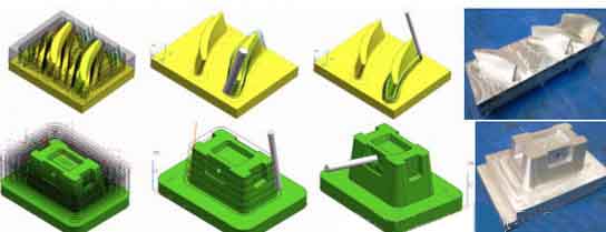
The UGII / Sequential Milling module can realize the control of each step in the tool path generation process, support 2~5 axis milling programming, and is completely related to the UGII master model. In an automated way, it obtains absolute control similar to APT direct programming, allowing users to interactively generate tool paths section by section, and maintain control of each step in the process. The provided cycle function allows users to define only the innermost and outermost tool paths on a certain surface, and the module automatically generates intermediate steps. This module is a unique UGII module with functions such as automatic root cleaning in the UGII CNC machining module, and is suitable for difficult CNC programming. As shown in Figure 4, the tool trajectories of 3-axis linkage and 5-axis linkage machining and the actual product processing are shown respectively.


