Several Correct Choices for Milling Thin Parts
In the fine machining of thin parts, the difference from rough machining is that the influence of clamping force, cutting tool and process parameters on the internal stress of the part must be fully considered in the finishing process. As well as the influence of cutting force and milling heat on the structure of the part during milling, the deformation is controlled to avoid the deformation caused by the efficiency improvement, which causes damage to the accuracy and surface quality of the part.
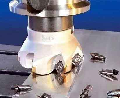
Selection of Cutting Tools for Machining Thin Parts
Choosing more reasonable tools can directly improve production efficiency. The milling of aluminum alloy materials does not require high tool materials. Generally, a cemented carbide milling cutter is sufficient, and the coating can be uncoated or diamond coated. In rough machining, since it is not necessary to consider the accuracy and quality issues, the metal material can be removed as efficiently as possible, so a large diameter tool can be selected to reduce the number of passes and shorten the pass time.
In addition, in rough machining, try to choose close-tooth tools instead of sparse-tooth tools, which can increase the feed per revolution, and the cutting speed can be increased at the same speed. In finishing machining, in addition to considering the problem of high-efficiency material removal, the problem of force and deformation control of thin-walled components during cutting should also be fully considered.
Carbide tools should be used for finishing high-strength aluminum alloy thin-walled parts. The rake angle of the tool should not be too small, otherwise the cutting deformation and friction will increase, the rake face wear will increase, and the tool life will be reduced. In addition, the selection of the arc radius of the tool tip should be appropriate, and the teeth of the tool should not be too dense to facilitate chip discharge. It is beneficial to further increase the feed rate, prevent the hardened layer from cold working, and prolong the service life of the tool.
Select the tool path for milling thin parts
A more effective way to increase speed and efficiency is to optimize the tool path, and ensure the directionality of the tool path during high-speed cutting. That is, the tool path is as simple as possible, with fewer turning points, and the path as smooth as possible to reduce rapid changes in direction; The idle time should be reduced, and the proportion of cutting time in the entire workpiece should be increased as much as possible;
Should try to use loop milling, through without interrupting the cutting process and tool path. Reduce the cutting-in and cutting-out times of the tool, and obtain a stable, efficient and high-precision machining process.
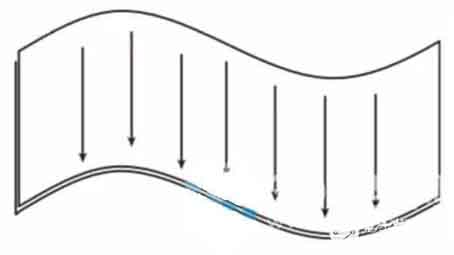
Tool path of small curvature radius surface
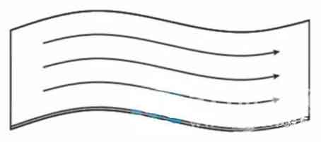
In the high-speed machining of large and complex curved surfaces of integral structural parts, when the curvature of the curved surface changes greatly, the direction of the maximum curvature radius should be used as the optimal cutting direction; When the curvature of the curved surface changes small, the influence of the radius of curvature on the cutting direction is weakened. It is better to choose the cutting direction with the longest average length of a single tool path.
Curved tool path with large radius of curvature
When machining inclined planes, if horizontal cutting is adopted, the cutting distance of each segment is very short. During the milling process, the spindle needs to change direction frequently, resulting in poor cutting stability. And because the milling is inclined, horizontal feed requires the linkage of X or Y axis and Z axis, which is not conducive to the increase of cutting speed.
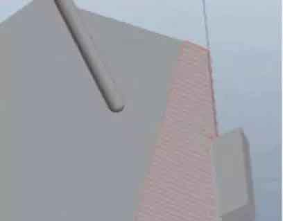
Therefore, for this type of bevel machining, the tool path should be arranged as parallel to the longest bevel as possible. Not only the tool path is the longest, the number of reversing times is the least, but the single tool is only cut in the X and Y planes. The movement in the Z-axis direction is arranged outside the contour of the workpiece, which can reduce tool damage even under high-speed cutting.

Oblique parallel tool path for milling
Selection of cutting parameters
In rough machining, you can generally choose a large feed rate and an appropriately large cutting depth, coupled with a medium cutting speed "high power" high-efficiency cutting, which can achieve a high material removal rate, thereby greatly improving production efficiency. For finishing, it is only feasible to increase the speed and increase the number of teeth. Increasing the feed per tooth may reduce the surface accuracy, resulting in residual stress and deformation. Therefore, "light cutting and fast cutting" with high cutting speed and low feed per tooth is often used to ensure the improvement of production efficiency and the accuracy and surface quality of products.
Cutting parameters can be determined by cutting finite element analysis and cutting tests. Take a gantry CNC machining center with a maximum spindle speed of 24000r/min as an example. Through the analysis of Third Wave AdvantEdge software, in the rough machining process of thin-walled panels, if you choose φ25mm or φ32mm indexable milling cutters. For the optimization of cutting parameters, the spindle speed should be appropriately increased, and the selection range is 12000~15000r/min; The feed per tooth and the cutting depth should not be too large, and the selectable ranges are respectively 0.15mm/z and 2~3mm.
Part of the milling test simulation data
The cutting test can be designed within the optional range of the parameters obtained from the finite element analysis, and the cutting efficiency, surface roughness, and machined surface topography are used as the evaluation criteria, and the optimal cutting parameters are finally selected.
Under the high-efficiency machining strategy of aluminum alloy thin-walled parts, the correct selection of the above-mentioned milling tools, cutting tools, and milling parameters is also required.


