How to solve the deformation of thin parts in CNC machining?
Turning and milling thin parts (aluminum, aluminum alloy, pure titanium, copper, magnesium alloy) are always prone to deformation during machining. Oval or "waist shape" with a small middle and large ends, which makes it difficult to ensure the quality of parts. Its clamping design is often the most discussed point. Let's take a look at two design examples of thin-walled fixtures on turning and milling parts, and how they solve the deformation problem.
Part. 1. Design a processing plan for thin-walled aluminum sleeve parts on a milling machine
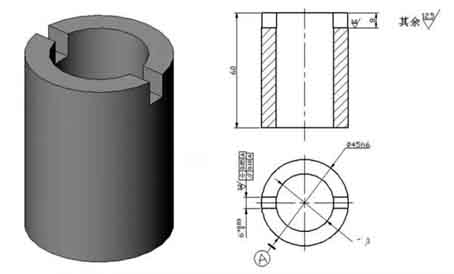
The aluminum thin-walled sleeve workpiece is shown in the figure, and the keyway width of 6mm is guaranteed by the keyway milling cutter; Grooves on both sides of a plane of symmetry axis of symmetry φ45 h6 0.05mm, 0.10mm parallelism; The groove depth is 8mm.
 Positioning plan and positioning components
Determine the positioning plan and select positioning components:
Clamping plan and clamping device design
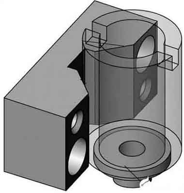
▲Clamping mechanism
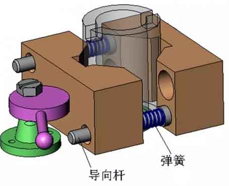 ▲Guide and automatic release device in the clamping mechanism
Design of parts fixture structure
1. Parts positioning device
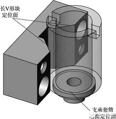
The long V-shaped block is the main positioning element in the fixture, eliminating 4 uncertainties of the workpiece. It can be found in relevant national standards or industry standards.
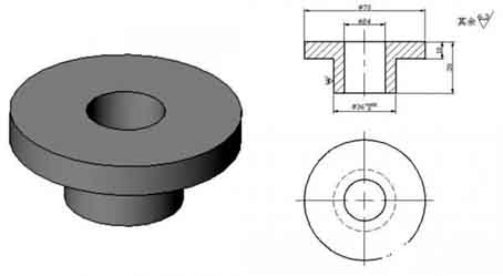
 Support sleeve:
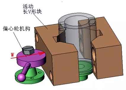
2. Parts clamping device
 ▲Eccentric wheel
 ▲Eccentric wheel bracket
3. assisting equipments
▲ Tool setting block of parts
4. Part clamping details
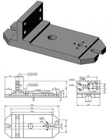
5. General drawing of parts fixture
1. Part clamping details
2. Cylindrical pin
3. Eccentric bracket
4. Eccentric
5. Movable V-shaped block
6. Tool setting block for parts
7. Fixed V-shaped block
Part. 2, Process plan for inner hole machining of aluminum alloy thin-walled parts
The workpiece is processed by seamless steel pipe. The surface roughness of the inner hole and the outer wall is Ra1.6μm, which can be achieved by turning, but the cylindricity of the inner hole is 0.03mm, which requires higher requirements for thin-walled parts. In mass production, the process route is roughly:
Material blanking — heat treatment — turning the end face — turning the outer circle — turning the inner hole — quality inspection.
The process of "processing the inner hole of the workpiece" is the key to quality control. We put aside the outer circle and thin-walled casing, it is difficult to guarantee a 0.03mm cylinder when the inner hole is cut.
The key technology of turning holes
The key technology of turning holes is to solve the rigidity and chip removal problems of the inner hole turning tool. To increase the rigidity of the inner hole turning tool, take the following measures:
1. Try to increase the cross-sectional area of the tool holder, usually the tip of the inner hole turning tool is located above the tool holder. In this way, the cross-sectional area of the tool holder is less, less than 1/4 of the cross-sectional area of the hole, as shown in the left figure below. If the tip of the inner hole turning tool is located on the center line of the tool holder, the cross-sectional area of the tool holder in the hole can be greatly increased, as shown in the right figure below.
2. The extension length of the tool holder can be 5-8mm longer than the length of the workpiece to increase the rigidity of the turning tool holder and reduce the vibration during the cutting process.
Solve chip evacuation problems
Mainly control the outflow direction of cutting chips. Rough turning tools require chips to flow to the surface to be machined (front chip removal). To this end, the inner hole turning tool with a positive edge inclination angle is used, as shown in the figure below.
In fine turning, the chip flow direction is required to be forward chip removal (hole core chip removal). Therefore, pay attention to the grinding direction of the cutting edge when sharpening the knife edge, and use the chip removal method that is inclined to the front edge. As shown in the figure below, the alloy used for fine turning tools is YA6. The current M type has better bending strength, wear resistance, impact toughness, and resistance to steel and temperature.
When sharpening, the rake angle is rounded with an arc-shaped angle of 10-15°, The relief angle is 0.5-0.8mm away from the wall according to the machining arc (the bottom line of the tool is along the arc), c Cutting edge angle k direction is §0.5-1 is along the chip edge, Point B wiper blade is R1-1.5, It is appropriate to grind the auxiliary back angle to 7-8°, The A-A point of the inner edge of E is ground into a circle to discharge chips.
Machining method
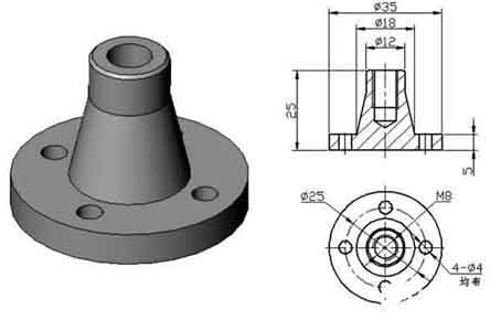
1. A guard shaft must be machined before machining. The main purpose of the shaft guard:
The inner hole of the turned thin-wall sleeve is sleeved in the original size, and the front and rear centers are fixed to make it process the outer circle without deformation, and maintain the quality and precision of the outer circle. Therefore, the processing of the shaft guard is a key link in the process of processing the thin-walled casing.
45﹟Carbon structure round steel for processing shaft guard blanks; Turning the end face, opening two B-shaped center holes, rough turning the outer circle, leaving a margin of 1mm. After heat treatment, tempering and shaping, and then fine turning, leaving a 0.2mm margin for grinding. Re-heat the crushed fire surface to a hardness of HRC50, and then grind it with a cylindrical grinder as shown in the figure below. After the accuracy meets the requirements, it is completed and ready for use.
2. In order to complete the processing of the workpiece at one time, the blank retains the clamping position and cutting margin.
3. Firstly, the rough embryo is heat-treated, quenched, tempered and shaped, with a hardness of HRC28-30 (hardness within the processing range).
4. The turning tool adopts C620, and first put the front center into the spindle cone to fix it. To prevent deformation of the workpiece when clamping thin-walled sleeves, add an open-loop thick sleeve, as shown in the figure below.
In order to maintain mass production, one end of the outer circle of the thin-walled casing is processed to a uniform size d, and the ruler of t is the axial clamping position. The thin-walled casing is clamped and compressed to improve the quality of turning the inner hole and maintain the size. Considering that cutting heat is generated, the expansion size of the workpiece is difficult to grasp. It is necessary to pour sufficient cutting fluid to reduce the thermal deformation of the workpiece.
5. Clamp the workpiece firmly with an automatic centering three-jaw chuck, turn the end face, and rough turn the inner circle. Leave a margin of 0.1-0.2mm for fine turning, and replace it with a fine turning tool to process the cutting margin until the guard shaft meets the requirements of excessive fit and roughness. Remove the inner hole turning tool, insert the guard shaft to the front center, use the tailstock center to clamp according to the length requirement, change the external turning tool, and rough turn the external circle. Finally, the precision turning parts meet the drawing requirements. After passing the inspection, use a cutting knife to cut according to the required length. In order to make the cut smooth when the workpiece is disconnected, the edge of the knife should be slant to make the end face of the workpiece smooth; The small part of the guard shaft is ground to cut the gap left. The guard shaft is to reduce the deformation of the workpiece, prevent vibration, and fall and bump when cutting off.
The above method for processing thin-walled casing solves the problem of deformation or causing size and shape errors to fail to meet the requirements. Practice has proved that the processing efficiency is high, easy to operate, and suitable for processing long thin-walled parts, the size is easy to grasp, the second completion, and the mass production is more practical.
Part. 1. Design a processing plan for thin-walled aluminum sleeve parts on a milling machine
The aluminum thin-walled sleeve workpiece is shown in the figure, and the keyway width of 6mm is guaranteed by the keyway milling cutter; Grooves on both sides of a plane of symmetry axis of symmetry φ45 h6 0.05mm, 0.10mm parallelism; The groove depth is 8mm.
Determine the positioning plan and select positioning components:
Clamping plan and clamping device design
▲Clamping mechanism
Design of parts fixture structure
1. Parts positioning device
The long V-shaped block is the main positioning element in the fixture, eliminating 4 uncertainties of the workpiece. It can be found in relevant national standards or industry standards.
2. Parts clamping device
3. assisting equipments
▲ Tool setting block of parts
4. Part clamping details
5. General drawing of parts fixture
1. Part clamping details
2. Cylindrical pin
3. Eccentric bracket
4. Eccentric
5. Movable V-shaped block
6. Tool setting block for parts
7. Fixed V-shaped block
Part. 2, Process plan for inner hole machining of aluminum alloy thin-walled parts
The workpiece is processed by seamless steel pipe. The surface roughness of the inner hole and the outer wall is Ra1.6μm, which can be achieved by turning, but the cylindricity of the inner hole is 0.03mm, which requires higher requirements for thin-walled parts. In mass production, the process route is roughly:
Material blanking — heat treatment — turning the end face — turning the outer circle — turning the inner hole — quality inspection.
The process of "processing the inner hole of the workpiece" is the key to quality control. We put aside the outer circle and thin-walled casing, it is difficult to guarantee a 0.03mm cylinder when the inner hole is cut.
The key technology of turning holes
The key technology of turning holes is to solve the rigidity and chip removal problems of the inner hole turning tool. To increase the rigidity of the inner hole turning tool, take the following measures:
1. Try to increase the cross-sectional area of the tool holder, usually the tip of the inner hole turning tool is located above the tool holder. In this way, the cross-sectional area of the tool holder is less, less than 1/4 of the cross-sectional area of the hole, as shown in the left figure below. If the tip of the inner hole turning tool is located on the center line of the tool holder, the cross-sectional area of the tool holder in the hole can be greatly increased, as shown in the right figure below.
2. The extension length of the tool holder can be 5-8mm longer than the length of the workpiece to increase the rigidity of the turning tool holder and reduce the vibration during the cutting process.
Solve chip evacuation problems
Mainly control the outflow direction of cutting chips. Rough turning tools require chips to flow to the surface to be machined (front chip removal). To this end, the inner hole turning tool with a positive edge inclination angle is used, as shown in the figure below.
In fine turning, the chip flow direction is required to be forward chip removal (hole core chip removal). Therefore, pay attention to the grinding direction of the cutting edge when sharpening the knife edge, and use the chip removal method that is inclined to the front edge. As shown in the figure below, the alloy used for fine turning tools is YA6. The current M type has better bending strength, wear resistance, impact toughness, and resistance to steel and temperature.
When sharpening, the rake angle is rounded with an arc-shaped angle of 10-15°, The relief angle is 0.5-0.8mm away from the wall according to the machining arc (the bottom line of the tool is along the arc), c Cutting edge angle k direction is §0.5-1 is along the chip edge, Point B wiper blade is R1-1.5, It is appropriate to grind the auxiliary back angle to 7-8°, The A-A point of the inner edge of E is ground into a circle to discharge chips.
Machining method
1. A guard shaft must be machined before machining. The main purpose of the shaft guard:
The inner hole of the turned thin-wall sleeve is sleeved in the original size, and the front and rear centers are fixed to make it process the outer circle without deformation, and maintain the quality and precision of the outer circle. Therefore, the processing of the shaft guard is a key link in the process of processing the thin-walled casing.
45﹟Carbon structure round steel for processing shaft guard blanks; Turning the end face, opening two B-shaped center holes, rough turning the outer circle, leaving a margin of 1mm. After heat treatment, tempering and shaping, and then fine turning, leaving a 0.2mm margin for grinding. Re-heat the crushed fire surface to a hardness of HRC50, and then grind it with a cylindrical grinder as shown in the figure below. After the accuracy meets the requirements, it is completed and ready for use.
2. In order to complete the processing of the workpiece at one time, the blank retains the clamping position and cutting margin.
3. Firstly, the rough embryo is heat-treated, quenched, tempered and shaped, with a hardness of HRC28-30 (hardness within the processing range).
4. The turning tool adopts C620, and first put the front center into the spindle cone to fix it. To prevent deformation of the workpiece when clamping thin-walled sleeves, add an open-loop thick sleeve, as shown in the figure below.
In order to maintain mass production, one end of the outer circle of the thin-walled casing is processed to a uniform size d, and the ruler of t is the axial clamping position. The thin-walled casing is clamped and compressed to improve the quality of turning the inner hole and maintain the size. Considering that cutting heat is generated, the expansion size of the workpiece is difficult to grasp. It is necessary to pour sufficient cutting fluid to reduce the thermal deformation of the workpiece.
5. Clamp the workpiece firmly with an automatic centering three-jaw chuck, turn the end face, and rough turn the inner circle. Leave a margin of 0.1-0.2mm for fine turning, and replace it with a fine turning tool to process the cutting margin until the guard shaft meets the requirements of excessive fit and roughness. Remove the inner hole turning tool, insert the guard shaft to the front center, use the tailstock center to clamp according to the length requirement, change the external turning tool, and rough turn the external circle. Finally, the precision turning parts meet the drawing requirements. After passing the inspection, use a cutting knife to cut according to the required length. In order to make the cut smooth when the workpiece is disconnected, the edge of the knife should be slant to make the end face of the workpiece smooth; The small part of the guard shaft is ground to cut the gap left. The guard shaft is to reduce the deformation of the workpiece, prevent vibration, and fall and bump when cutting off.
The above method for processing thin-walled casing solves the problem of deformation or causing size and shape errors to fail to meet the requirements. Practice has proved that the processing efficiency is high, easy to operate, and suitable for processing long thin-walled parts, the size is easy to grasp, the second completion, and the mass production is more practical.


