Advanced technology of thread turning
Why is thread turning so demanding?
The requirements for thread turning are higher than ordinary turning operations. The cutting force is generally higher, and the cutting end radius of the threaded insert is smaller and weaker.
In thread processing, the feed rate must correspond exactly to the pitch of the thread. For a pitch of 8 threads/inch (tpi), the tool must advance at a feed rate of 8 revolutions/inch or 0.125 inches/revolution. Compared with ordinary turning applications (where the typical feed rate is about 0.012ipr), the feed rate of thread turning is 10 times higher. The force at the tip of the threaded processing insert may be 100 to 1,000 times higher.
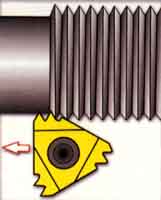
figure 2: Multi-tooth inserts, with multiple thread teeth in a series, thread processing efficiency may be improved, but the cutting force is higher.
The end radius that bears this force is generally 0.015 inches, while the radius of a conventional turning insert is 0.032 inches. For threaded tools, the radius is strictly limited by the root radius of the permitted thread shape (its size is specified by the relevant thread standard). It is also limited by the required cutting action, because the material cannot withstand the cutting process in ordinary turning, otherwise thread deformation will occur.
The result of higher cutting force and narrower force concentration range is: Thread machining inserts bear much higher stress than general turning tools.
Comparison of partial and full profile blades
Partial profile inserts, sometimes referred to as "non-topped" inserts, cut thread grooves without cresting or cresting the thread. (See Figure 1) A tool can produce a series of threads, up to the thickest pitch-that is, the smallest number of threads per inch-which is permitted by the strength of the blade end radius.
The end radius is designed to be small enough that the blade can process various pitches. For small pitch threads, the end radius will appear to be too small. This means that the blade must penetrate deeper when machining. For example, machining an 8 tpi thread with a partial profile insert requires a thread depth of 0.108 inches. The same thread produced with a full profile blade requires only a specified depth of 0.81 inches. Therefore, the full profile insert can produce a stronger thread. In addition, the operation of machining threads with full profile inserts can be done in 4 less steps.
Multi-tooth blade
The multi-tooth blade has a series of teeth continuously, and the cutting depth of any tooth in the thread groove is deeper than the previous tooth. (See Figure 2) With these inserts, the number of operations required to machine a thread can be reduced by 80%. The tool life is much longer than single-center inserts, because the final tooth only processes half or one-third of the metal of a given thread.
However, due to their high cutting force, it is not recommended to use these inserts for the processing of thin-walled parts-because chatter may occur. In addition, the structure for machining workpieces with these inserts must have sufficient thread clearance so that all teeth can exit cutting.

Figure 4: Flank transverse cutting does not produce V-shaped chips, but produces chips similar to those in ordinary turning.
Feed per thread
The cutting depth of each pass, or the feed of each thread, is very critical in thread processing. Each connected operating channel must engage the larger part of the cutting edge of the blade. If the feed per pass is constant (this method is not recommended), the cutting force and metal removal rate will increase drastically from the previous pass to the next.
For example, when using a constant feed of .010 inches / processing speed of a channel 60 ℃ thread shape, the second track material is removed 3 times the first track. As with each subsequent operation, the amount of metal removed continues to rise exponentially.
In order to avoid this increase in the amount of removal and maintain a more realistic cutting force, the thread depth should be reduced with each operation.
Cross-cut thread feed method
There are at least four thread crosscut feeding methods. (See Figure 3) Few people have discovered how much impact one of these methods has on the effectiveness of threading operations.
• Radial thread crosscut feed
•Although this may be the most commonly used method for thread processing, it is indeed the least recommended method. Since the tool is fed radially (perpendicular to the centerline of the workpiece), the metal is removed from both sides of the thread flank, resulting in V-shaped chips. Such chips are difficult to break, so the flow of chips is a problem. In addition, due to the higher heat and pressure on both sides of the blade end, the tool life is usually shorter than other cross-cutting feed methods.
• thread flank cross feed
In this method, the transverse direction is parallel to one of the flank of the thread, which generally means that the tool feeds in a straight line at 30°C. Chips are similar to those produced in ordinary turning. (See Figure 4.) Compared with radial crosscutting, the chips produced in this method are easier to shape and are easily discharged from the cutting edge, with better thermal diffusion. However, in this cross-cutting feed method, the trailing edge of the blade rubs against the tooth flank and does not cut. This will burn the threads, resulting in poor surface roughness and even chattering.
• Modified thread tooth flank transverse cutting feed (recommended)
This method is similar to the thread flank transverse cutting feed method, except that the transverse cutting angle is smaller than the thread angle-that is, less than 30 ℃. This method retains the advantages of the thread flank transverse cutting method, while avoiding the problems caused by the trailing edge of the blade. A cross-cut angle of 291/2 ℃ generally produces the best results, but in actual operation, a cross-cut angle in the range of 25~291/2 ℃ is acceptable.
Figure 5: By adjusting the blade helix angle, such as the "inclined" blade on the right, the clearance angle under the front and back edges of the blade can be balanced, which can produce more uniform wear.
• Alternate thread flank transverse cutting feed
This method alternately feeds along the two flank of the thread, so it uses the two flank of the blade to form the thread. This method can guarantee a longer tool life, because both sides of the blade end are used. But it can also cause chip flow problems —
This problem may affect the surface roughness and tool life. This method is usually only used for large pitch and (imperial) trapezoidal and oblique quadrilateral threads.
Clearance thread angle compensation
Certain thread machining inserts and tool holder systems have the ability to accurately tilt the insert in the cutting direction by changing the helix angle. This feature can produce higher-quality threads because it prevents the blade from rubbing against the flank of the thread. It can also provide longer tool life because the cutting force is evenly distributed over the entire length of the cutting edge.
There is no cutting insert that is inclined in this way- The way to make the cutting edge parallel to the centerline of the workpiece- An unequal clearance angle will be formed under the leading edge and trailing edge of the blade. (See Figure 5) Especially for thicker pitches, this disparity may cause friction in the tooth flank.
The adjustable system allows the angle of the blade to be tilted through the positioning of the tool chuck (usually with shims). Precise adjustment will achieve similar leading and trailing edge angles, ensuring uniform development of blade wear.
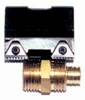 Figure 6: This custom thread cutting tool is used to machine two independent threads on a six-spindle lathe. In the past, threads were processed one at a time. The insert used here was actually originally intended for thread milling cutters, but it is used here as a turning insert
Miniaturization and specialization of thread cutting inserts
Indexable insert-type tools for turning internal threads on holes with a diameter of approximately 0.3 inches are now available on the market.
There are many advantages to machine such small holes into threads by turning. The thread quality to be machined is usually relatively high, the blade structure allows chips to flow out of the hole and rarely damages the thread, and the blade can be indexed, so the tool cost is low.
The grades of cemented carbide used in these applications are generally those that allow processing at lower surface speeds. For internal thread machining in small holes, the limitations of machine tools are generally other problems than low surface speeds.
The technological advances that people have made have expanded the scope of application of thread turning tools, and the turning of internal threads into small holes is one example. However, despite the expansion of the scope of application of standard tools, manufacturers still have to encounter specific problems, which creates room for the existence of customized tools. (See Figure 6) The special tool developed in cooperation with the tool supplier is an option that cannot be ignored when searching for the correct threading tool for a specific job.
The requirements for thread turning are higher than ordinary turning operations. The cutting force is generally higher, and the cutting end radius of the threaded insert is smaller and weaker.
In thread processing, the feed rate must correspond exactly to the pitch of the thread. For a pitch of 8 threads/inch (tpi), the tool must advance at a feed rate of 8 revolutions/inch or 0.125 inches/revolution. Compared with ordinary turning applications (where the typical feed rate is about 0.012ipr), the feed rate of thread turning is 10 times higher. The force at the tip of the threaded processing insert may be 100 to 1,000 times higher.
figure 2: Multi-tooth inserts, with multiple thread teeth in a series, thread processing efficiency may be improved, but the cutting force is higher.
The end radius that bears this force is generally 0.015 inches, while the radius of a conventional turning insert is 0.032 inches. For threaded tools, the radius is strictly limited by the root radius of the permitted thread shape (its size is specified by the relevant thread standard). It is also limited by the required cutting action, because the material cannot withstand the cutting process in ordinary turning, otherwise thread deformation will occur.
The result of higher cutting force and narrower force concentration range is: Thread machining inserts bear much higher stress than general turning tools.
Comparison of partial and full profile blades
Partial profile inserts, sometimes referred to as "non-topped" inserts, cut thread grooves without cresting or cresting the thread. (See Figure 1) A tool can produce a series of threads, up to the thickest pitch-that is, the smallest number of threads per inch-which is permitted by the strength of the blade end radius.
The end radius is designed to be small enough that the blade can process various pitches. For small pitch threads, the end radius will appear to be too small. This means that the blade must penetrate deeper when machining. For example, machining an 8 tpi thread with a partial profile insert requires a thread depth of 0.108 inches. The same thread produced with a full profile blade requires only a specified depth of 0.81 inches. Therefore, the full profile insert can produce a stronger thread. In addition, the operation of machining threads with full profile inserts can be done in 4 less steps.
Multi-tooth blade
The multi-tooth blade has a series of teeth continuously, and the cutting depth of any tooth in the thread groove is deeper than the previous tooth. (See Figure 2) With these inserts, the number of operations required to machine a thread can be reduced by 80%. The tool life is much longer than single-center inserts, because the final tooth only processes half or one-third of the metal of a given thread.
However, due to their high cutting force, it is not recommended to use these inserts for the processing of thin-walled parts-because chatter may occur. In addition, the structure for machining workpieces with these inserts must have sufficient thread clearance so that all teeth can exit cutting.
Figure 3: The choice of cross-cutting feed method has a great influence on thread processing efficiency
Figure 4: Flank transverse cutting does not produce V-shaped chips, but produces chips similar to those in ordinary turning.
Feed per thread
The cutting depth of each pass, or the feed of each thread, is very critical in thread processing. Each connected operating channel must engage the larger part of the cutting edge of the blade. If the feed per pass is constant (this method is not recommended), the cutting force and metal removal rate will increase drastically from the previous pass to the next.
For example, when using a constant feed of .010 inches / processing speed of a channel 60 ℃ thread shape, the second track material is removed 3 times the first track. As with each subsequent operation, the amount of metal removed continues to rise exponentially.
In order to avoid this increase in the amount of removal and maintain a more realistic cutting force, the thread depth should be reduced with each operation.
Cross-cut thread feed method
There are at least four thread crosscut feeding methods. (See Figure 3) Few people have discovered how much impact one of these methods has on the effectiveness of threading operations.
• Radial thread crosscut feed
•Although this may be the most commonly used method for thread processing, it is indeed the least recommended method. Since the tool is fed radially (perpendicular to the centerline of the workpiece), the metal is removed from both sides of the thread flank, resulting in V-shaped chips. Such chips are difficult to break, so the flow of chips is a problem. In addition, due to the higher heat and pressure on both sides of the blade end, the tool life is usually shorter than other cross-cutting feed methods.
• thread flank cross feed
In this method, the transverse direction is parallel to one of the flank of the thread, which generally means that the tool feeds in a straight line at 30°C. Chips are similar to those produced in ordinary turning. (See Figure 4.) Compared with radial crosscutting, the chips produced in this method are easier to shape and are easily discharged from the cutting edge, with better thermal diffusion. However, in this cross-cutting feed method, the trailing edge of the blade rubs against the tooth flank and does not cut. This will burn the threads, resulting in poor surface roughness and even chattering.
• Modified thread tooth flank transverse cutting feed (recommended)
This method is similar to the thread flank transverse cutting feed method, except that the transverse cutting angle is smaller than the thread angle-that is, less than 30 ℃. This method retains the advantages of the thread flank transverse cutting method, while avoiding the problems caused by the trailing edge of the blade. A cross-cut angle of 291/2 ℃ generally produces the best results, but in actual operation, a cross-cut angle in the range of 25~291/2 ℃ is acceptable.
Figure 5: By adjusting the blade helix angle, such as the "inclined" blade on the right, the clearance angle under the front and back edges of the blade can be balanced, which can produce more uniform wear.
• Alternate thread flank transverse cutting feed
This method alternately feeds along the two flank of the thread, so it uses the two flank of the blade to form the thread. This method can guarantee a longer tool life, because both sides of the blade end are used. But it can also cause chip flow problems —
This problem may affect the surface roughness and tool life. This method is usually only used for large pitch and (imperial) trapezoidal and oblique quadrilateral threads.
Clearance thread angle compensation
Certain thread machining inserts and tool holder systems have the ability to accurately tilt the insert in the cutting direction by changing the helix angle. This feature can produce higher-quality threads because it prevents the blade from rubbing against the flank of the thread. It can also provide longer tool life because the cutting force is evenly distributed over the entire length of the cutting edge.
There is no cutting insert that is inclined in this way- The way to make the cutting edge parallel to the centerline of the workpiece- An unequal clearance angle will be formed under the leading edge and trailing edge of the blade. (See Figure 5) Especially for thicker pitches, this disparity may cause friction in the tooth flank.
The adjustable system allows the angle of the blade to be tilted through the positioning of the tool chuck (usually with shims). Precise adjustment will achieve similar leading and trailing edge angles, ensuring uniform development of blade wear.
Miniaturization and specialization of thread cutting inserts
Indexable insert-type tools for turning internal threads on holes with a diameter of approximately 0.3 inches are now available on the market.
There are many advantages to machine such small holes into threads by turning. The thread quality to be machined is usually relatively high, the blade structure allows chips to flow out of the hole and rarely damages the thread, and the blade can be indexed, so the tool cost is low.
The grades of cemented carbide used in these applications are generally those that allow processing at lower surface speeds. For internal thread machining in small holes, the limitations of machine tools are generally other problems than low surface speeds.
The technological advances that people have made have expanded the scope of application of thread turning tools, and the turning of internal threads into small holes is one example. However, despite the expansion of the scope of application of standard tools, manufacturers still have to encounter specific problems, which creates room for the existence of customized tools. (See Figure 6) The special tool developed in cooperation with the tool supplier is an option that cannot be ignored when searching for the correct threading tool for a specific job.


